Grimston Page 4
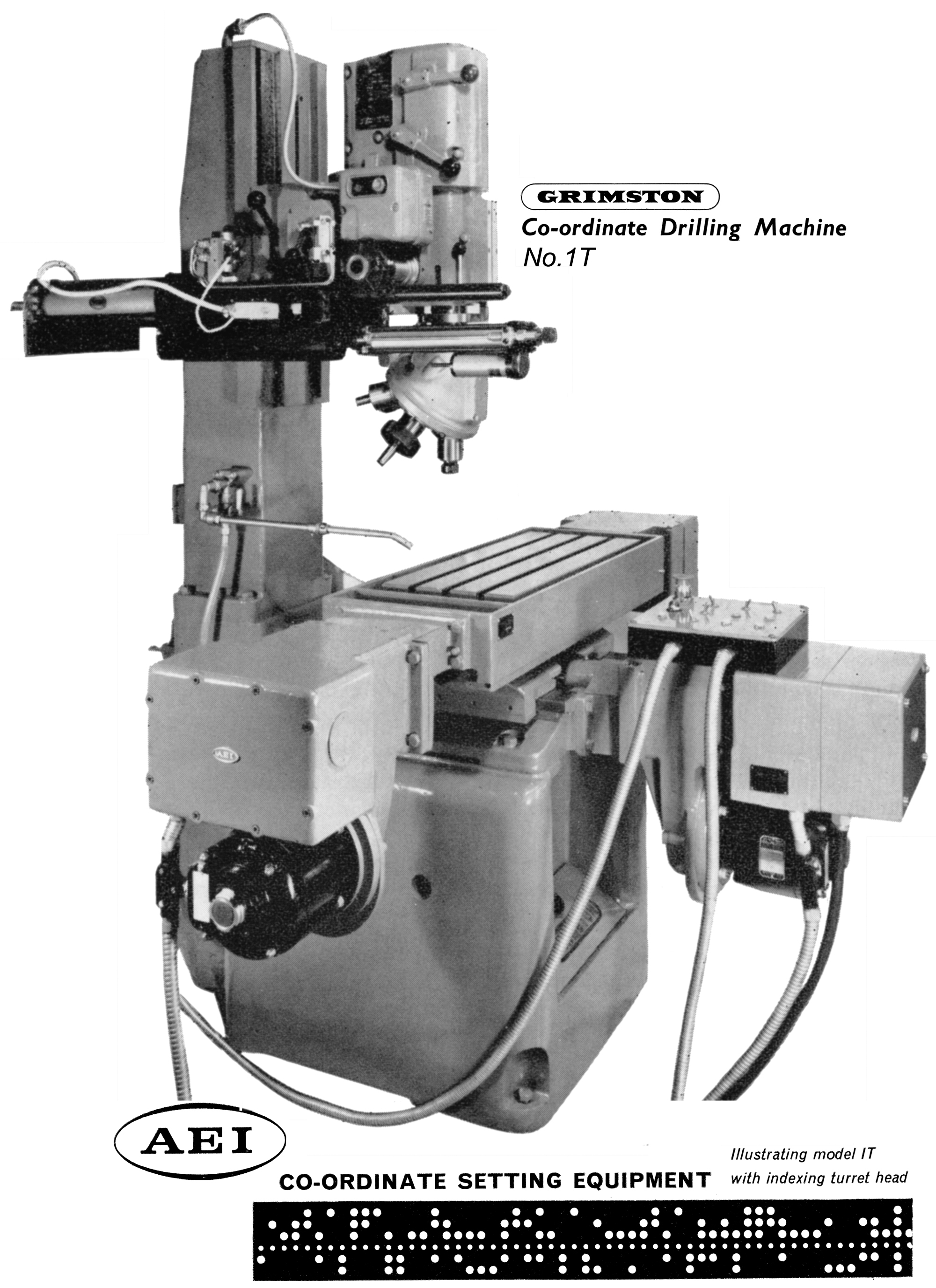
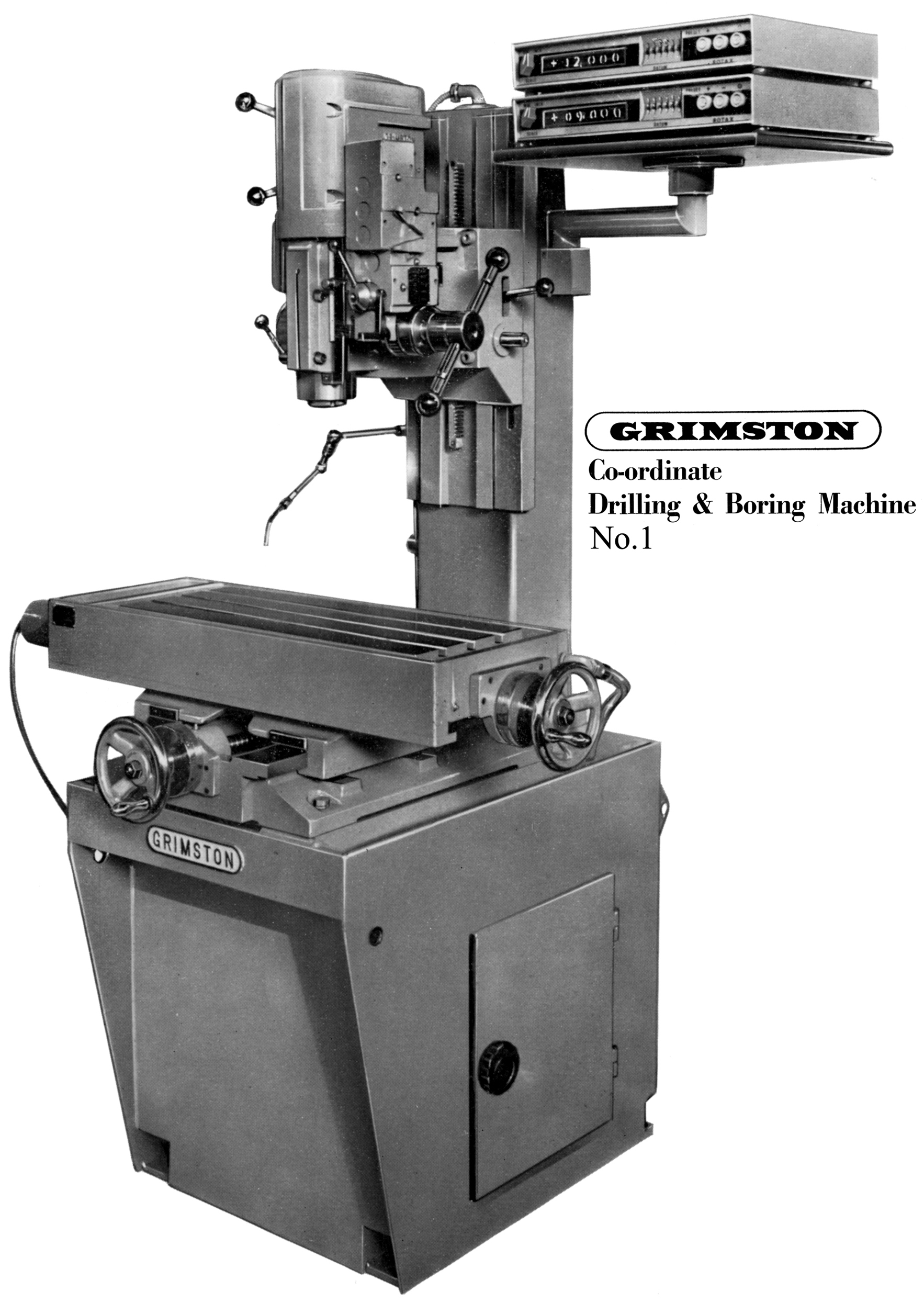
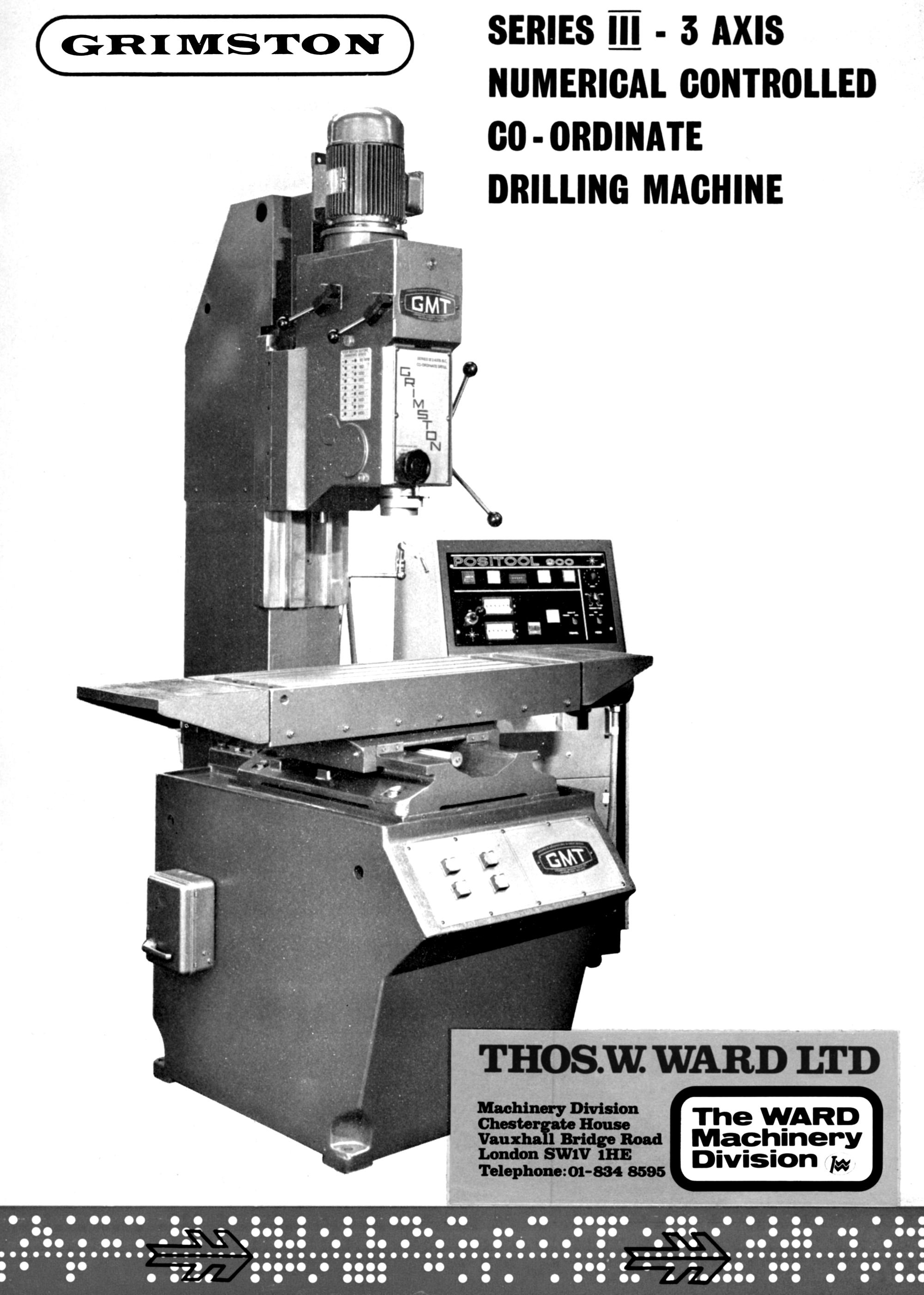
A product of the early 1970s, the Grimston Co-ordinate drilling machine was built in two models, the No.1 and a modified version, the No.1T.
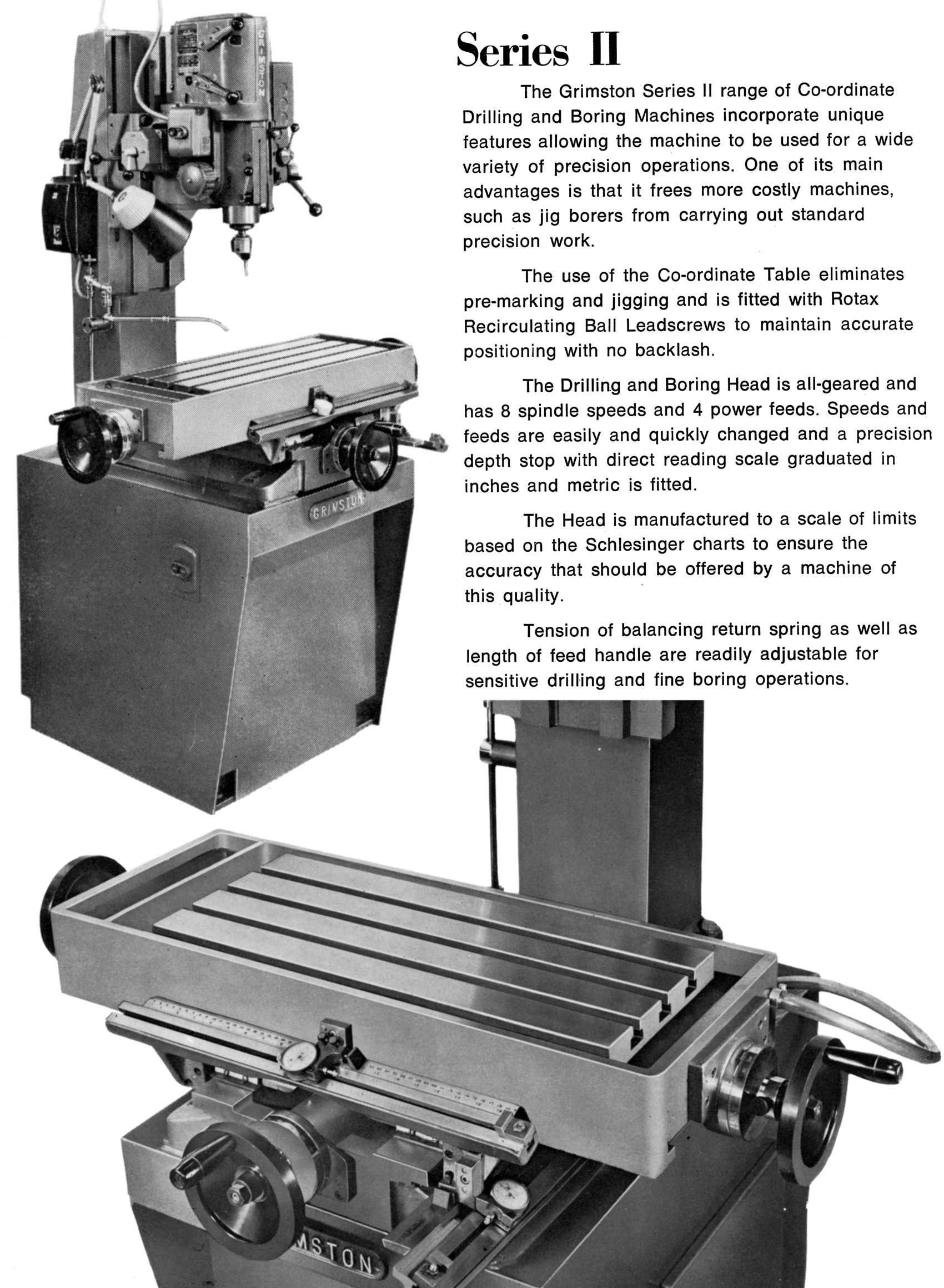
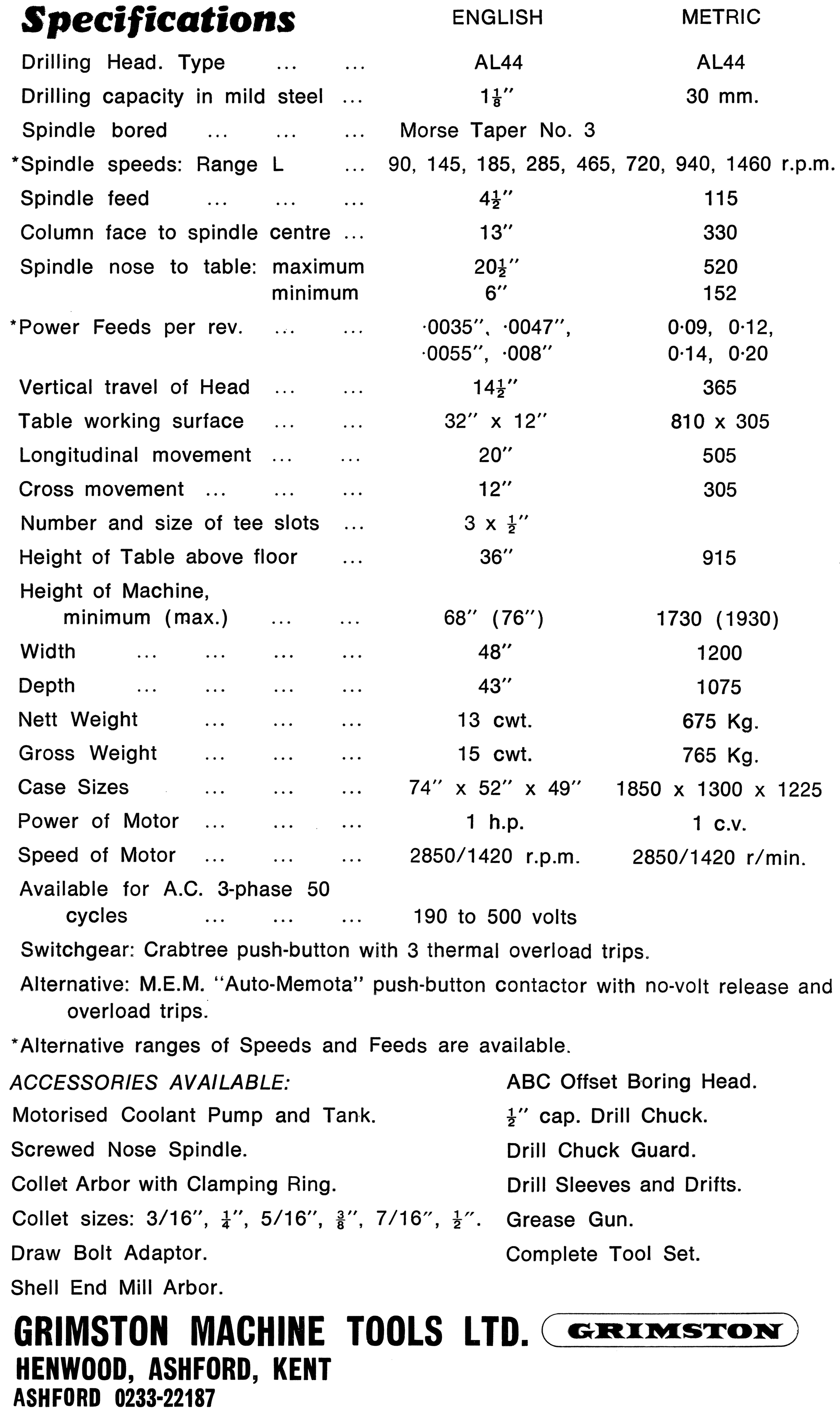
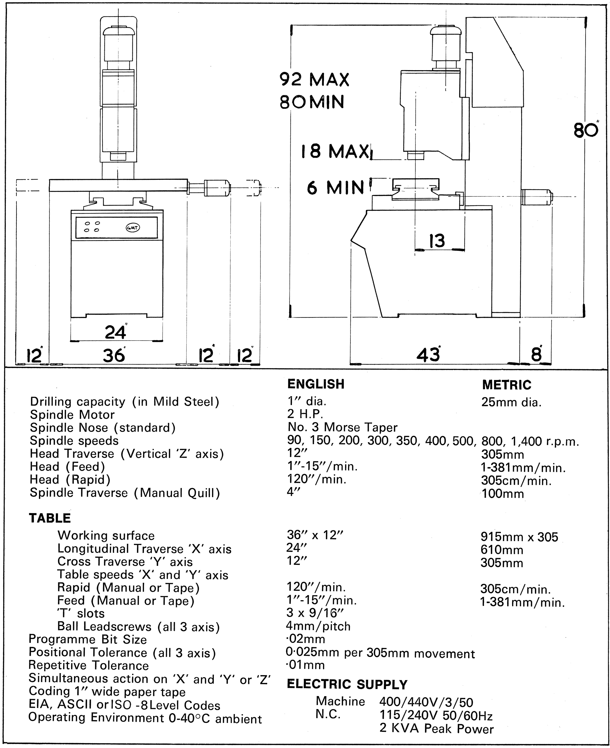
The No. 1 was a single-spindle machine that used a standard, 1-inch capacity, Type L44L Grimston drilling head fitted with a No. 3 Morse taper spindle and with eight speeds from 90 to 1460 r.p.m. The throat was 12 inches and the distance to the column 13".
A production machine built to special order, the No.1T was could be equipped with either a four, five or six station indexing turret head - each with a drilling capacity of 5/8" inch. Various spindles were offered including step-up, reduction-geared and ones for tapping.
On both the No.1 and No.1T power came from a built-in, 415-volt, 3-phase, 50 Hz motor with control by a safety, no-volt release, push-button starter with thermal overload trips.
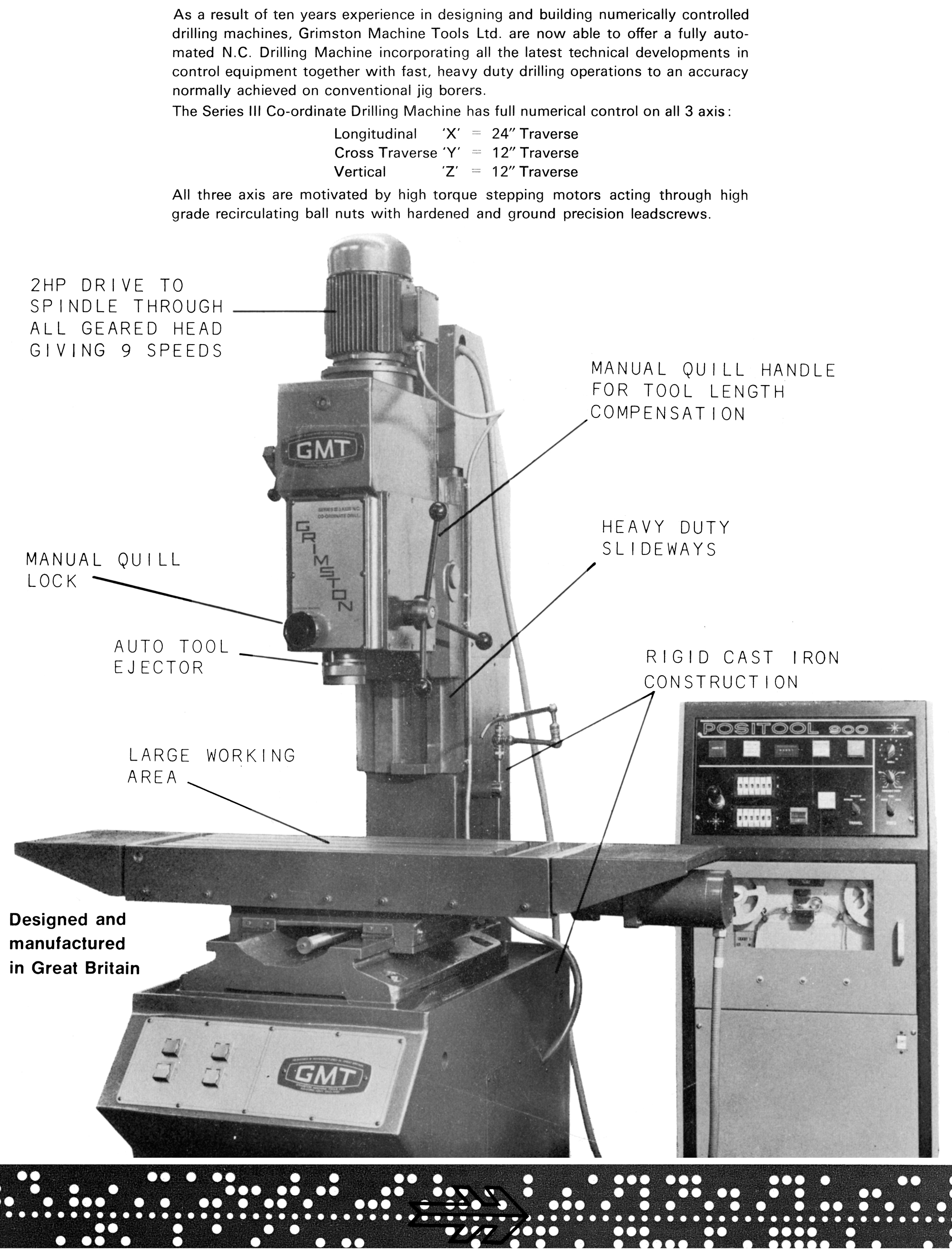
Carried on a substantial, box-section column in cast iron, the drilling head was locked in place by double clamps and moved vertically through its 14-inch travel by manually operated, rack and pinion gearing. The maximum clearance between the spindle nose to table top was 25 inches.
Spindle travel, instead of being hand or mechanically fed, was by an electrically controlled, air-hydraulic feed unit that incorporated vernier control for governing the feed depth and position checking. Fast approach and quick return was included and controlled in either direction by built-in air-flow regulators. Setting of the drilling depth was claimed to be simple and the unit easily and quickly re-adjusted; for very fast drilling the rate of feed was controlled by "valve-speed" controls and fitted with what was described as a "hydrocheck" unit, this being to "check" the drill as it broke through the job.
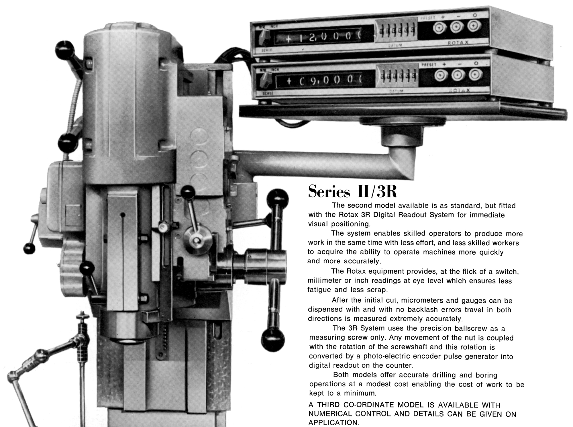
With a working space of 32" x 12", the co-ordinate table had T-slots covering an area of 24" x 9". Longitudinal travel was 20 inches, in traverse 12 inches - with both driven by re-circulating ball screws of 0.2" pitch. Coupled to each feedscrew was a 0.5 h.p. motor that drove through epicyclic gearing and magnetic clutches. Two Data Boxes were provided that housed the necessary rotary encoders to measure the absolute rotation of the leadscrew; a printed circuit board for decimal/binary conversion was also fitted, its purpose being to reduce the number of wires required between the console and data box.
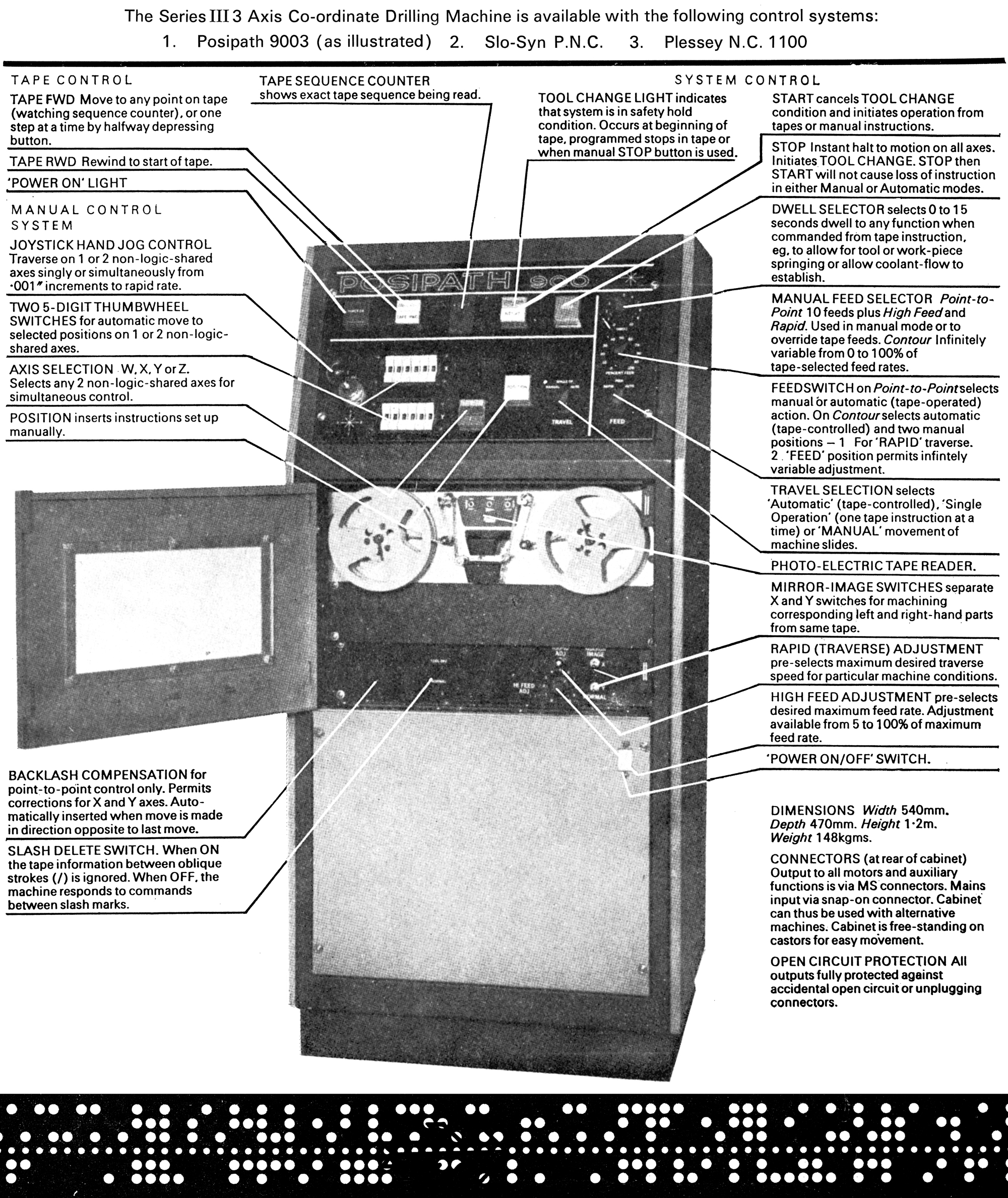
The cabinet was of substantial construction and fitted with a removable front panel that allowed access to the (optional-extra) electric coolant pump and tank. A switch panel was also provided, this having all the necessary controls independent of the control console. Floor-mounted, the main control console housed all necessary circuitry and power supplies with the electronic circuits assembled on plug-in printed circuit boards using solid-state components.
Mounted on the top of the control console, the tape-reader unit wired into the control giving automatic control from the 40-feet of punched paper tape that was provided as standard - this providing enough capacity for around 300 machining operations. The tape code (around which the standard equipment was designed) was an EIA 8 track - though others were also available.
Picture are high-resolution and may take time to load