|
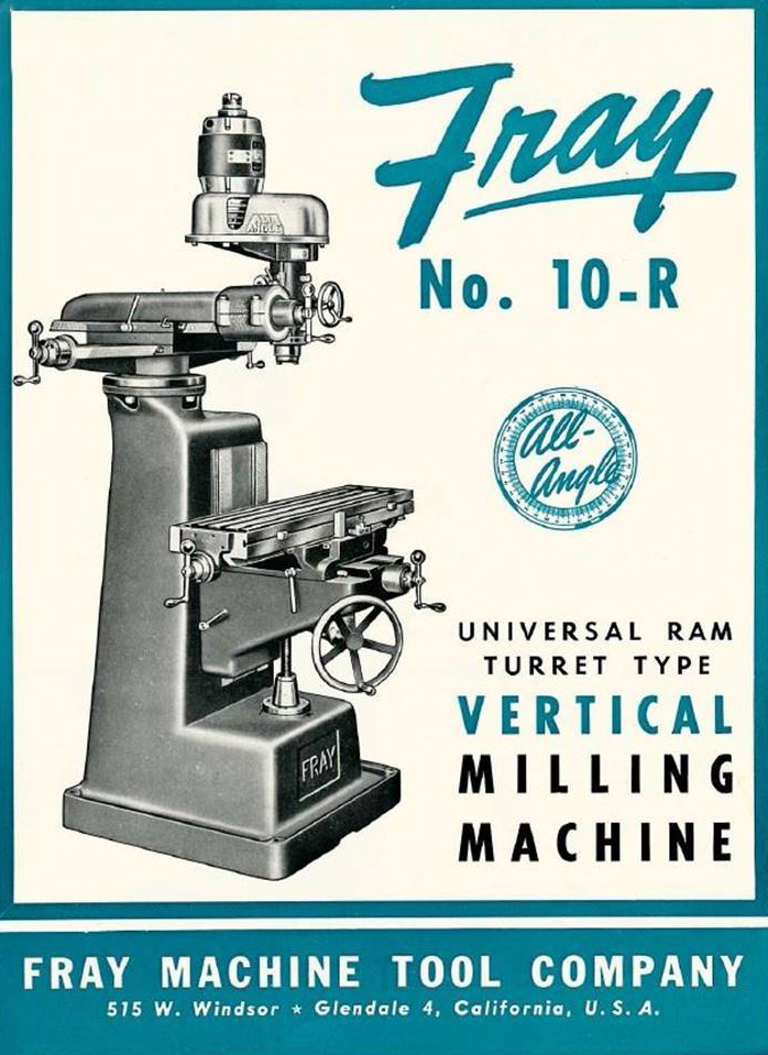
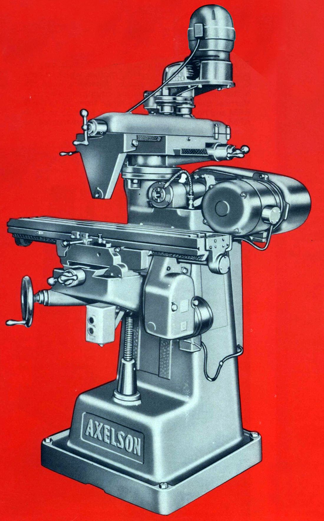
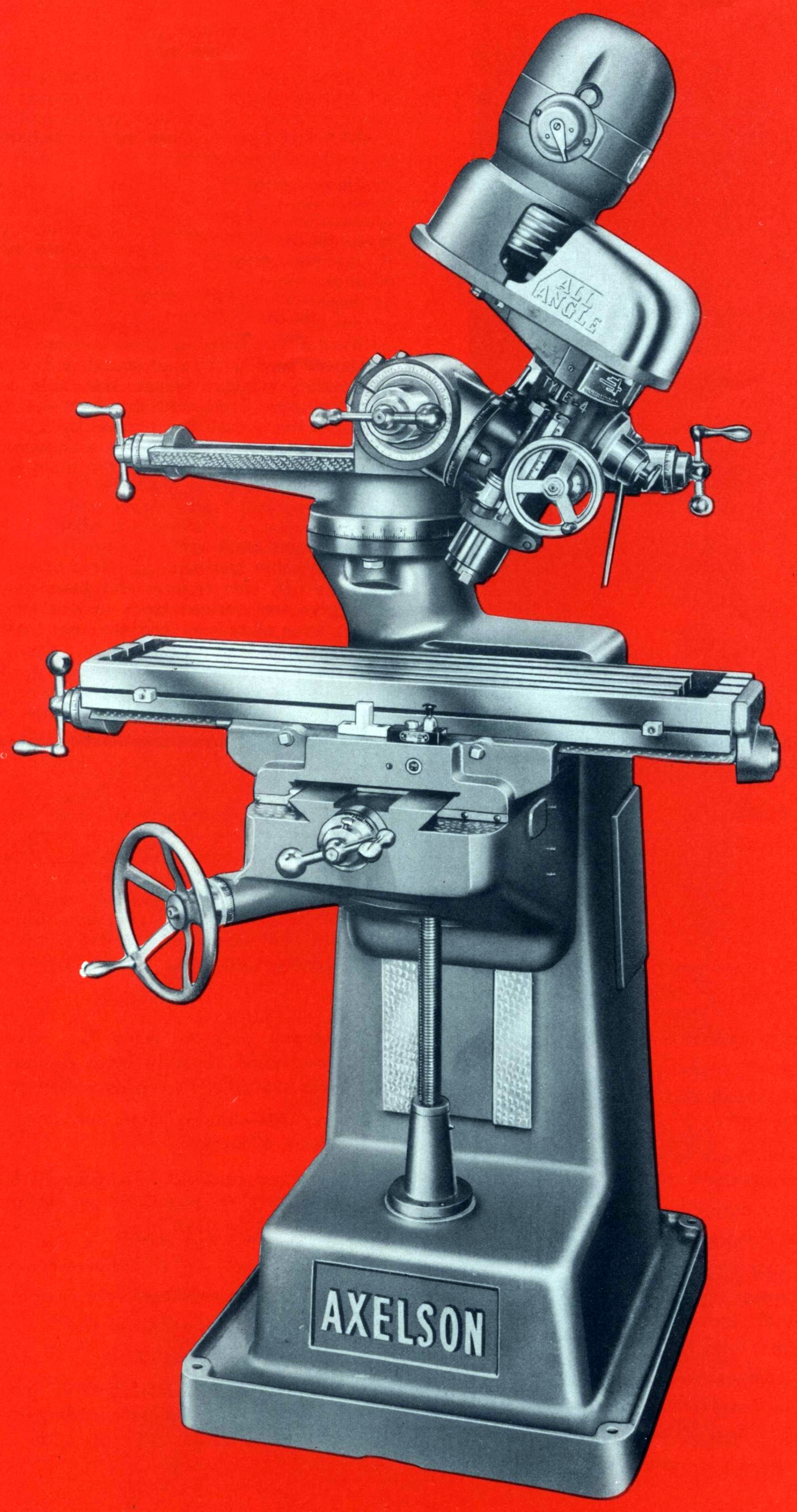
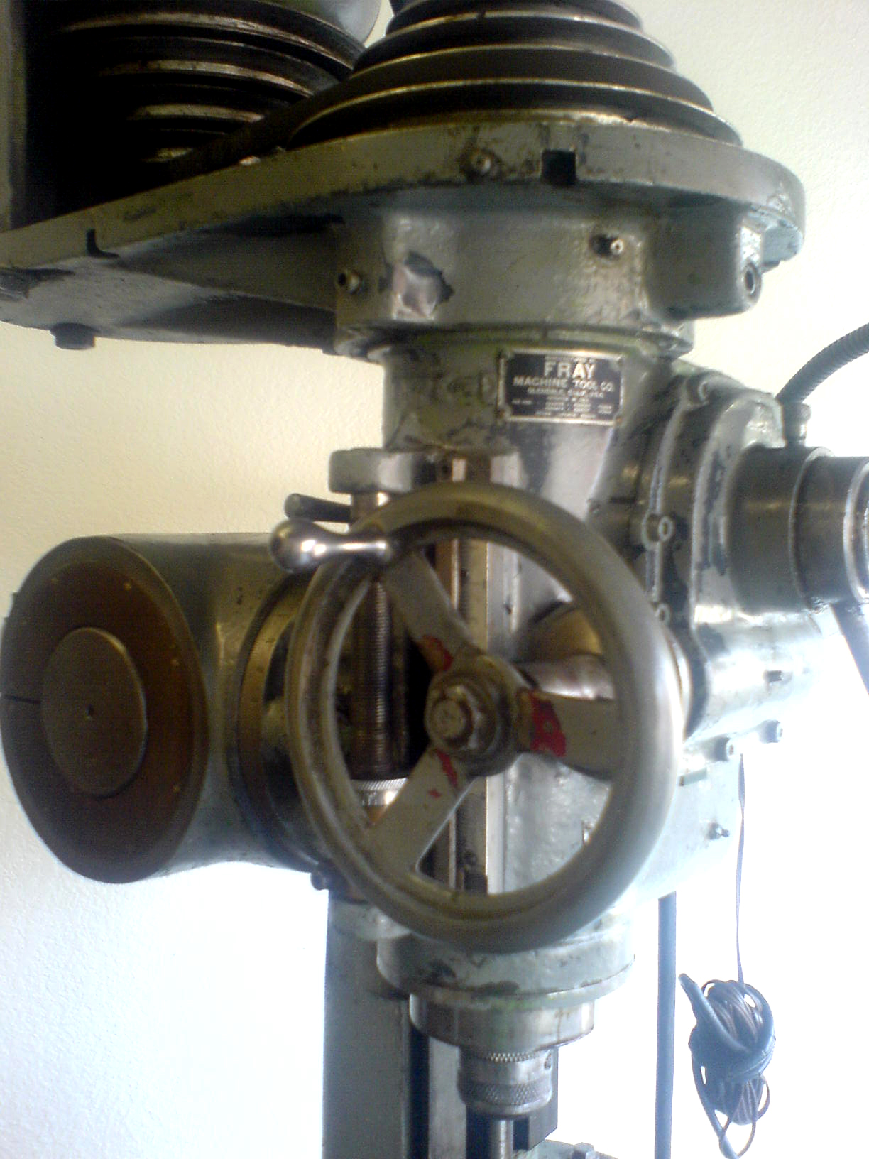
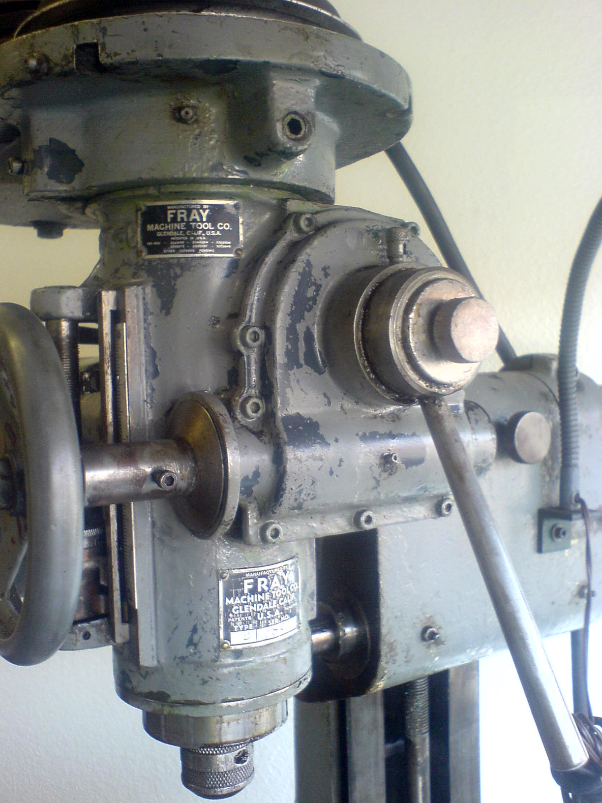
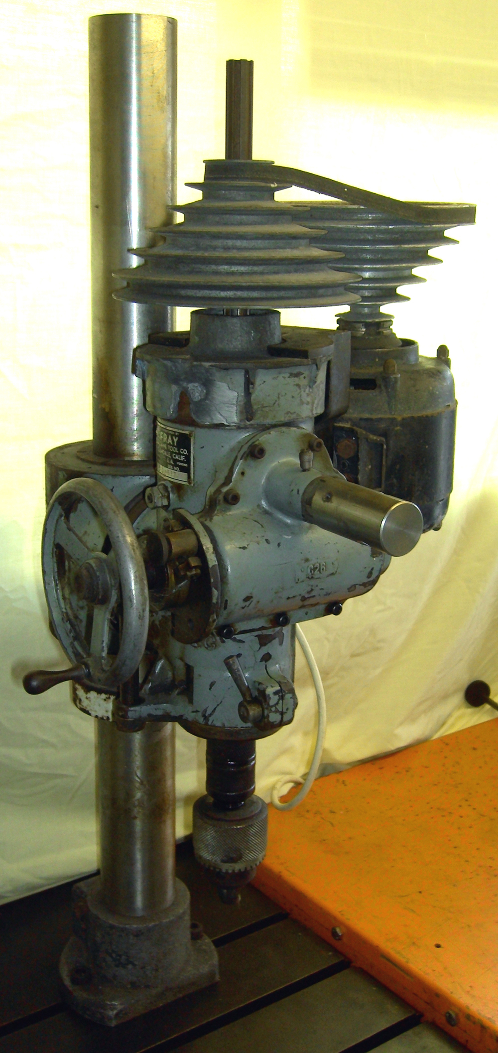
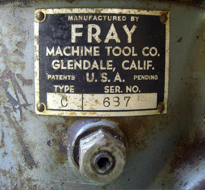
Manufactured by the Fray Machine Tool Company of 515 West Windsor Road, Glendale 4, California, the Fray "All-Angle" universal milling machine, together with a number of different vertical heads, were produced from the late 1930s to (probably) the mid 1950s. The Fray was also badge engineered, with some examples carrying plates engraved for the machine tool company Axelson, the model types listed being the 10RH (vertical and horizontal) and the 10R (vertical only). The miller was also sold in an adapted form as the Diamond RU36 with both horizontal and vertical capacity and a generally heavier ram and head assembly - the latter incorporating belt-driven power down-feed to the spindle. The Diamond and Fray Companies being relative close to each other in Glendale, it is likely that some sort of licensing or cooperation deal was done, or possibly the owner of Fray moved to Diamond after his factory closed.
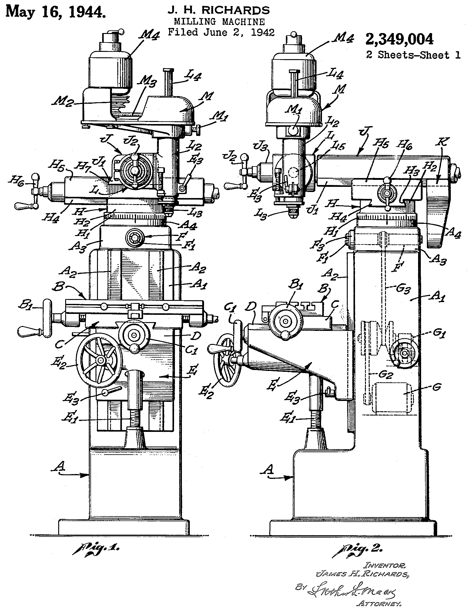
All Fray millers were designed by an Englishman (born in Hale, Lancashire), James H. Richards, a man who was to become president and CEO of the Company. Mr. Richards also held patents for an inside/outside micrometer, a pneumatic grease gun and a form of worm-drive steering gear. A grandson of steam engine inventor Richard Trevithick, he could recall, as a little boy, playing with parts of a Trevithick steam engines that were laying around the family barn
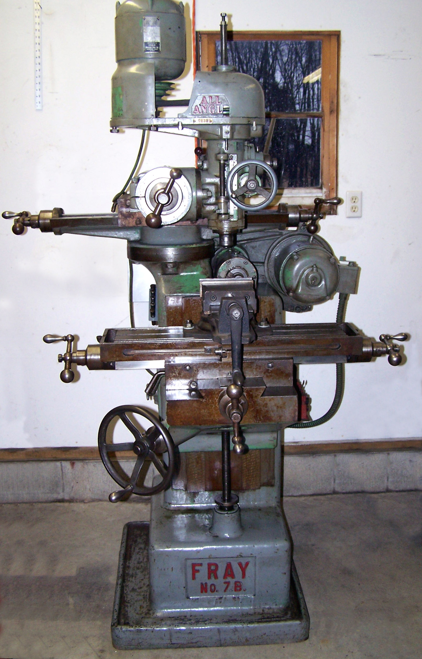
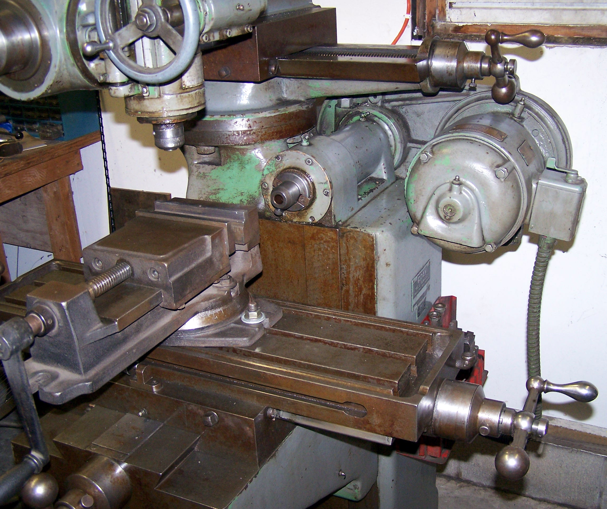
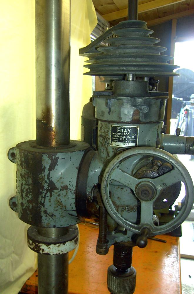
Heavily built, the main column of the Fay carried, on its top, a large boss that could be swivelled through 360 degrees around the vertical axis and on which was mounted a horizontal slideway. Running on the slide was a large block that (on the 10-RH) supported both an overarm for horizontal-milling and a sliding ram fitted with a self-contained, Bridgeport-like, backgeared, 8-speed swivelling head fitted with fine down-feed and a drilling quill. The drive for horizontal milling was arranged by mounting the swivelling head well to one side of the main column to make room for a simply-constructed arrangement that consisted of a semi-steel housing that held a 30-International taper spindle with a motor mounted parallel to it. To help customers, Fray offered adaptors to convert the regular 30-International taper to either a No. 7 B & S, or a No. 2 or 3 Morse. Otherwise almost identical to the RH, the Model 10-R lacked a horizontal-drive arrangement.
Because the vertical head (known on these models as the Type 4) was able to be rotated through 360 degrees in two planes vertical to the table, through 90 degrees forwards or backwards - and also moved in and out and from side to side - the machine was extremely versatile and able to machine complex jobs that, on an ordinary horizontal miller (or even on a turret type)) would have needed resetting more than once before finishing.
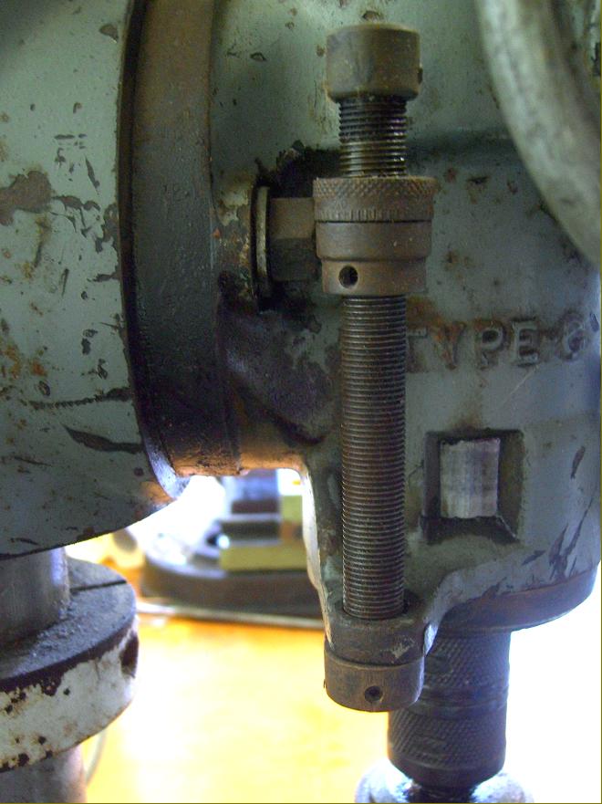
Made in a "semi-steel" cast-iron, the spindle housing had a honed bore to accept the sliding quill with the spindle manufactured from a chrome-moly steel, hardened and ground all over and running in 3 'New Departure' No. 5 precision, pre-loaded angular-contact bearings. Of alloy steel, the quill housing was heat treated and ground on both its inner and outer diameters and under the control of both a rapid-feed rack-and-pinion operated handle and a 34 : 1 ratio worm-and-gear fine feed mechanism- with an instantaneous change available between the two.
With a 1 H.P. 1200 rpm motor, and equipped withnthe optional "backgear" assembly, 8 speeds were available from 100 to 4500 rpm; with the alternative 1.5 H.P 1800 rpm motor the speed range became 150 to 6400 rpm; however, only the two lowest speeds were driven through the 3 : 1 ratio backgear, the other six being by direct V-belt drive. An electrical reversing switch was standard equipment.
Also running in high-precision bearings, the horizontal spindle was driven through its eight speeds of 280, 640, 980, 1470, 2250 and 3600 rpm by a 1 H.P. 1700 r.p.m. motor. The ram carrying the head had a forwards and backwards travel of 10 inches on the 10-R but, restricted by the provision of the horizontal spindle, a reduced movement of 8.5 inches on the 10-RH. The side to side movement of the head was 16 inches and this, combined with the table's normal longitudinal movement, contributed to a maximum combined travel of 38 inches.
Identical in size on both the 10-RH and 10-R, the table had three T-slots, and was 36" long and 9" wide with longitudinal and cross travels of 22 and 8 inches respectively - and a vertical movement of 16 inches. The zeroing micrometer feed dials were all generously proportioned - a full 3 inches in diameter - with all the feed screws supported on adjustable, friction-reducing radial-thrust bearings. The saddle-to-knee ways were particularly large and both that surface, and the table's, were lubricated by a "one-shot" system supplied from a hand-pump..
If any reader has a Fray machine tool, or literature about the Company and its products, the writer would be interested to hear from you..
|
|