E-MAIL   Tony@lathes.co.uk
Home   Machine Tool Archive   Machine-tools for Sale & Wanted
Machine Tool Manuals   Machine Tool Catalogues   Belts   
Books   Accessories

Excel No. 1 Jig Borer & Machine Dimensions
Elliott/Downham Home Page  Mk.3 Downham     

Excel Mini Jig Borer Swivel Head Model   Excel Die Miller   

Mini Jig Borer Belts Replacement

An Instruction Manual is available for these machines

Jig Boring Machines & Techniques   Jig Boring Training

Used by the B. Elliott Machinery Group, the Excel name indicated items of better-than-average quality and usually directed towards a specialised segment of the market; it was adopted by various of the Elliott brands, including Victoria, Cardiff, Progress and Invicta to market lathes, millers, small jig borers, die milling machines, precision filing & sawing machines, tool & cutter and surface grinders and  other machine tools from the 1930s until the 1960s, . 
A straightforward copy of the American Liney Jig borer, the standard Excel No. 1 used, like all others of its kind, a fixed compound table and relied for all vertical movements on a quill-feed head that ran up and down on ways machined into the inner face of a heavy, cast-iron column. The head, of massive proportions for its capacity, was counterbalanced by a weight hanging from a roller chain and wire inside the column. The only way of moving the head assembly through its 8 inches of travel was by hand, there being no rack or gear feed; however, with great ingenuity, instead of the original American designers allowing the weight to balance just the head they also arranged for the chain to lift in the middle of a flat bar that connected to both the head casting and the quill - so counterbalancing the latter and helping to reducing backlash (a similar mechanism being employed on one of the smaller Swiss SIP jig borers). Another, very rare version of the Excel has been found with the top section of the main column arranged to swivel on a massive boss; this arrangement, while adding to the machine's versatility, unfortunately precluded incorporating the head balancing mechanism. The writer has only encountered two examples of this model and, if you have one, he would be delighted to hear from you
A 0.5 h.p. 1425 rpm motor was generally fitted, this being fastened on a plate at the back of the column to drive forwards by "A" section V-belts via a ball-bearing supported and adjustable intermediate pulley to the main head - the system giving a useful range of eight speeds: 225, 350, 475, 740, 1000, 1700, 2000 and 3400 rpm.  The drive was enclosed by a front-hinged guard, stayed by a two-part tie bar, that neatly and safely covered all three pulleys and both belts.
With a quill travel of 3-inches, the distance from its centre to the column ways (the throat) was 5.75-inches. The spindle assembly - beautifully made in nickel-chrome steel - was heat treated, ground all over, lapped on its bearing surfaces and help in high-precision bearings that were claimed to need no adjustment in service and which were provided with fifty pounds of pre-load pressure. To obtain perfect concentricity the outer diameter of the quill and the spindle nose were finish ground while running in their own bearings - and to prevent the spindle suffering interference from pull by the drive belt, its pulley (mirroring the arrangement used on many high-class lathes) ran on an independent set of ball races.
Collets were held in the quill by a compression nut on the nose - and could be had in sizes from 1/8" to 1/2" in increments of 1/32". Unfortunately, these collets were of the ordinary split-from-one-end type and so limited the machine's usefulness as a light-duty vertical miller - any sideways forces on the cutter causing them to work loose unless only the most judicious of cuts was taken. In recognition of the fact that so tempting a small machine would (unless locked in a strong room) be pressed into service as a milling machine, the Linley company went on to equip their version with Schaublin Type ESX collets which, being split from both ends had a vastly-superior gripping ability. In a similar vein the much later British Downham/Elliott version of the could be had quipped with an alternative collet set into which milling cutters could be screwed. If you have one of these machines and wish to mill check the collets page to see if any company can help. Early models used collets as the Brown & Sharpe 00 or 00A, catalogue numbers 4996 and 5071.
Continued below:


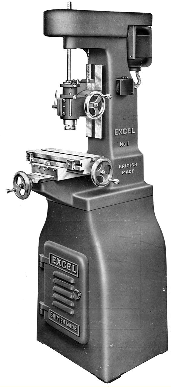
Almost an exact copy of the early Linley Jig Borer the Excel No. 1 was marketed using one of the B. Elliott Machine Tool Group's "Generic" names.
The machine was supplied on a heavy-cast-iron stand and

Continued:
In order to ease the operator's workload on boring operations the head was fitted with a very useful Direct-reading Micrometer Depth Gauge with a graduated bar that passed through a boss on the side of the casting.  Its method of operation was simple: to machine to a depth of 1.167 inches the cutting tool was set in contact with the work and the bar moved until it was at any even line. The stop-screw was then lowered until it made contact with the top of the bar - and the locking thumb screw tightened. The dial was set to zero, locked and then the bar lowered 11 divisions; the cut could now be made until the stop-screw was met. If the stop-screw was then released the remaining distance of 0.067" could be accurately measured by using the down-feed dial.
15-inches long and 5.5-inches wide, the hand-scraped table (with a single central T-slot) had travels of 10-inches longitudinally and 6-inches laterally while the maximum distance from the spindle nose to the surface was 9-inches.
Because the machine was in three sections - base cabinet, knee section and main column - it was possible to introduce a distance piece between the two upper parts and so increase the spindle to table distance by around 4 inches. The sides of the table slideways were square, not dovetailed, and all the 'working' flat and sliding surfaces of the machine were hand-scraped to a precision fit. The machine weighed approximately 700 lbs..


In order to ease the operator's workload on boring operations the head was fitted with a very useful Direct-reading Micrometer Depth Gauge with a graduated bar passing through a boss on the side of the casting.  Its method of operation was simple: to machine to a depth of 1.167 inches the cutting tool was set in contact with the work and the bar moved until it was at any even line. The stop-screw was then lowered until it made contact with the top of the bar - and locked. The dial was set to zero, locked and then the bar lowered 11 divisions; the cut could now be made until the stop-screw was met. If the stop-screw was then released the remaining distance of 0.067" could be accurately measured by using the down-feed dial.

Downham (Elliott and Gate) Mini Jig Borer
Co-ordinate Drilling & Milling Machine
DIMENSIONS
Mini Jig Borer Home Page

Dimensions Mk. 1 Machines

T-slot dimensions Mk. 1

Dimensions Mk. 2 Machines

Above: dimensions for the Mk. 2 Downham Jig Borer

Table T slots and a plan elevation of machine's stand dimensions Mk. 2 and Mk. 3 Models


Above: dimensions for the Mk. 3 Downham Jig Borer

Table T slots and a plan elevation of machine's stand dimensions Mk. 2 and 3

Excel No. 1 Jig Borer & Machine Dimensions
Elliott/Downham Home Page   Mk.3 Downham     

Excel Mini Jig Borer Swivel Head Model   Excel Die Miller

Mini Jig Borer Belts Replacement

An Instruction Manual is available for these machines

Jig Boring Machines & Techniques   Jig Boring Training