email: tony@lathes.co.uk
Home   Machine Tool Archive   Machine-tools Sale & Wanted
Machine Tool Manuals   Catalogues   Belts   Books  Accessories

DIMCO Lathes

DIMCO D.B.C. 175 Lathe - Page 2    DIMCO 225 Lathe


Dimco, based in Milan, Italy, were once a well-known manufacturer of machine tools and had branches in London, New York, Caracas and Buenos Ayres. Their range included grinders, power presses and lathes, the latter all of industrial quality and size and popular from the 1940s until the 1960s.  Typical of the company's products were the "Model D.B.C. 175" (described below) and the larger  "D.G.M 225"
The D.B.C. 175, with a 6
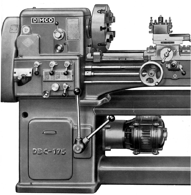
7/8-inch centre height and a between-centres capacity of 39 inches, was a well specified and heavily-built lathe advertised as being suitable for both toolroom and production work. Unlike most makers of the period, who fitted their lathes to fabricated sheet-metal or cast-iron stands, Dimco cast their machines as a single unit with the bed and its two supporting columns fabricated from one large pattern. Even the floor-level section that braced the headstock-end plinth and tailstock foot was usefully employed as the coolant tank. The close-grain, cast-iron V-way bed was 105/8-inches wide with multiple lattice-like cross braces between the front and back walls. A 7-inch long removable gap was provided as standard and, when lifted out, enabled a piece of metal up to 20¾-inches in diameter and 4½ -inches deep to be turned on the faceplate.
Inside the headstock-end plinth, and driven by a 3 hp motor flange-mounted externally to its right-hand face, was the 4-speed spindle-drive gearbox. Mounting a self-contained box in this position, with drive to the headstock by belts, was intended to reduce vibrations associated with meshing gears from being transmitted to the workpiece and was usually a design employed on better-quality toolroom lathes -  its use in a more modestly-priced lathe was unusual, though not unique. The gearbox contained two alloy-steel shafts running in ball races and carrying hardened and ground gears with lubrication by splash and centrifuge.  Built into the drive flange between electric motor and box was a clutch and brake unit that used a combination of brake shoes and cast-iron expansion rings; this assembly allowed the spindle to be stopped and started by the control of a single lever mounted concentrically with the speed change lever on the front face of the headstock-end plinth.
The headstock was of box form, in grey cast iron and internally ribbed for greater rigidity. It carried a case hardened, tempered and ground 1
3/8-inch bore (5-Morse taper) spindle that ran in a 2.9-inch diameter by 4.5-inch long adjustable front bronze bearing and a pair of ball races at the rear that were also arranged to take end thrust. Built into the front section of the headstock was a splash-lubricated, hardened and ground backgear assembly that gave a low-speed range of: 26, 44, 74, and 126 rpm and a high of: 220, 352, 592 and 1000 rpm. A special high-speed model with a maximum of 2000 rpm was also available but this required a different spindle, probably running on roller races front and rear, and had to be specially ordered. Unfortunately the spindle nose was a simple thread - and this at a time when machines of similar capacity from the likes of Colchester, Harrison, LeBlond and Delta-Rockwell had been available with the much-superior American long-nose taper for some years.
Continued below:

Strongly built and completely self-contained in the manner of most industrial lathes built from the mid 1940s onwards

Continued:
Apart from an opening in the front to allow the use of a sliding tumbler selector the screwcutting and feeds gearbox was completely enclosed and lubricated by splash from an oil bath. Lubricant was designed to be flung into the roof of the box where it settled into cast-in troughs positioned directly above the various bearings from where it could be directed by drillings. To ensure that only clean oil drained down short pipes were fitted into each hole so allowing any dirt or swarf to settle undisturbed into the bottom of the trough. All shafts were made from case-hardened steel and ground and the special alloy steel gears heat treated. Changes of pitch and rates of power feed were made separately with the former altered by the juxtaposition of 4 levers in combination with the sliding selector and the latter by a rotary knob with 5 settings available without altering the gear train. The leadscrew was used only for screwcutting and the power feeds transmitted to the apron through a separate shaft protected by "ball-and-spring" overload clutch. The sliding rate ranging from approximately 0.002" through 0.004", 0.008", 1/64" to 1/32" per revolution of the spindle with the surfacing feed set at half those rates. Both feeds (but not screwcutting pitches) could be instantly changed without any need to stop the lathe. The gearbox was able to generate 34 metric threads from 0.2 to 7 mm pitch, 28 inch threads from 56 to 4 t.p.i., 13 Modulus threads from Mod 0.25 to 3.5 and 28 Diametric threads from 112 to 6 pitch.
The apron was a model of mechanical simplicity with the leadscrew clasped by twin nuts and the keyed power shaft passing through and driving a bevel gear that transmitted its motion to a set of spur gears. A single lever control on the face of the apron both selected and engaged the feeds and, because the mechanism did not become loaded under heavy cuts, it was possible to flick the drive in and out as required.  A shallow oil trough ran along the top of the casting into which were inserted short tubes (possibly with wicks) though clean oil could be skimmed off to reach the various shafts.
Pivoting on the right-hand face of the apron was a conveniently positioned lever connected by a "third-rod" control to the spindle start, stop and reverse switch.
The saddle carried T slots in all four wings but, because bed ways stopped beneath the spindle nose the compound slide rest had to be positioned towards the saddle's headstock end in order to get the cutting tool right up to the faceplate. Both top and cross slides were adjusted with taper gib strips, carried ball thrust bearings on their feed screws and had clearly engraved zeroing micrometer dials with narrow knurled grip rings. The handles were traditional "balanced-ball" type that, whilst handsome, might have been considered rather hard on the operator's hands on a machine of this size.
With a No. 3 Morse taper the tailstock was correctly sized to the machine but the use of a direct-bearing screw to lock the spindle was unusual for the time when nearly every other lathe of this size had a compression fitting that squeezed top and bottom. The spindle also lacked either a graduated collar or ruler engravings to assist the operator gauge drilling and boring depths.
The lathe was 84 inches long, 33 inches wide and, equipped with its normal accessories, approximately 2645 lbs.
In 1952 the DIMCO 172 sold for £907 (about half the contemporary price of a UK house and twice average national earnings) and came with the following standard equipment: 2 spare gears to vary the screwcutting range, 14-inch independent 4-jaw chuck, electric motor and switchgear, fixed and travelling steadies, coolant pump and distribution piping, light unit, catch plate, headstock centre adaptor, centres for headstock and tailstock, adjustable carriage stop, a collection of 7 spanners including a "C" type to adjust the spindle front bearing..

The floor-level section of the cast-iron stand was usefully employed as the coolant tank. The 3-hp motor was flange-mounted to the right-hand face of the headstock-end plinth.

Unlike most makers of the period, who fitted their lathes to fabricated sheet-metal or cast-iron stands, Dimco cast their machines as a single unit with the bed and its two supporting columns in one large piece

The 4-speed spindle-drive gearbox was mounted inside the base of the headstock-end plinth.. The box contained two alloy-steel shafts running in ball races and carrying hardened and ground gears with lubrication by splash and centrifuge. A combined clutch and brake was built into the drive flange.


DIMCO D.B.C. 175 Lathe - Page 2    DIMCO 225 Lathe

DIMCO Lathes
email: tony@lathes.co.uk
Home   Machine Tool Archive   Machine-tools Sale & Wanted
Machine Tool Manuals   Catalogues   Belts   Books  Accessories