|
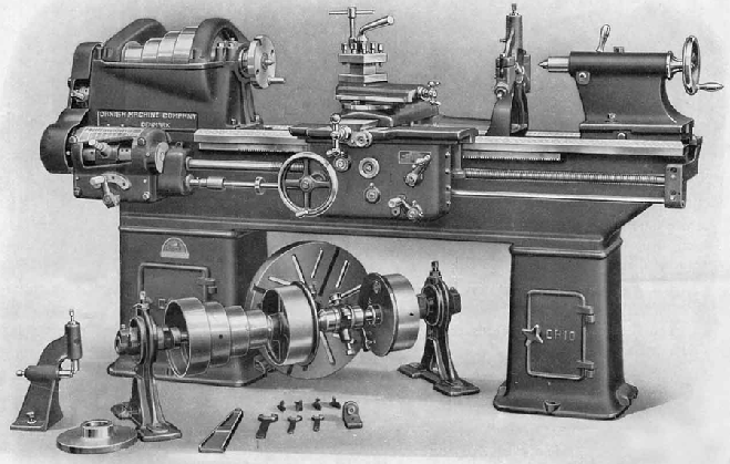
Owned by a Mr. J.E.Rasmussen, the Danish Machiner Company had works at Aabyhøj, near Århus. The firm manufactured a range of machine tools and often traded under, or employed, the DAMACO trade mark- a name that may have represented an Association of Danish machine-tool companies (today the little "Damco Five" Bench Lathe is more often found than the larger models). Lathes were imported to the UK by J. L. Brookland Machinery of Birmingham - but the surviving records cover just two of Mr. Rasmussen's lathes, the 9-inch centre height "Ohio" together with sparse details of a much smaller and unnamed bench machine. The larger lathe was of typically 1920s appearance with an 8-speed, backgeared headstock, 28-inch capacity gap bed and a Norton-type quick-change screwcutting gearbox with the sliding selector carried on an internal round bar not unlike the kind used for many years on the "Regal" models made by LeBlond.
For the class of machine the bed was unusually deep; it had two V and two flat ways, was 13.75 inches wide and available in three lengths that gave between-centres capacities of 40, 60 and 80 inches. the bed was supported on cast-iron box-cabinets under both headstock and tailstock with, on the two longer-bed versions, an additional box support under the middle of the bed. Although a gap was provided as standard (and the base of the bed was closed, with right-angle cross bracing) a straight bed could also be specified in which case (because it would almost certainly be used for heavy-duty production work) the option was available to have the base left open (to allow chips to fall though) and the cross bracing positioned diagonally.
With front and back walls arranged to stiffen the assembly by reaching up to the centre of the bearings, the headstock held a ground-finish, 15/8"-bore spindle manufactured from "crucible" steel (a term expressing quality more commonly used in the late 1800s and early 1900s) that ran in 3-inch diameter by 4-inch long adjustable bronze bushes at both front and rear. End thrust was taken by a ball race and the backgear assembly used a quick-release method where the bull wheel was held to the face of the drive pulley by a quickly-released, spring-loaded plunger. The pulley, which was turned all over and, for smoothness of running, carefully balanced, had four rather than the more common 3 steps, each 4 inches wide. Although he headstock gave a total of 8 speeds the standard countershaft provided with the lathe doubled this to 16. It was fitted with two input pulleys, both able to spin on the shaft or be locked to it by interconnected toggle arms that engaged one pulley whilst simultaneously disengaging the other; the countershaft would have been connected to two different size pulleys on an overhead line-shaft system to give both high and a low-speed ranges with the change made from one to the other merely by operating a foot or hand control linked (by wires or rods) to the toggle arms.
Drive to the screwcutting gearbox was by the usual changewheels and through an externally-mounted tumble-reverse mechanism - although, on lathes of this size - and from this era - these rather highly-stressed gears was often inside the left-hand face of the headstock where they could be better supported and lubricated. The box was able to generate 44 English pitches from 3 to 44 t.p.i, including 19 t.p.i, and feeds from 0.125 to 2 mm per revolution of the spindle; a set of metric conversion changewheels was included with the lathe and allowed the most popular metric pitches to be cut. All the gears in the box, except the largest one, were of high quality steel (though not hardened) and: "of wide face and coarse pitch." The leadscrew was
A separate powershaft was provided to run the sliding and surfacing feeds and, providing the spindle speed was not too high, the makers claimed that changes from one pitch to the other, and from one feed-rate to another, could be made without stopping the motor. It is likely that the lathe was fitted with an adjustable automatic disengage to the carriage drive.
Doubled-walled, the apron was provided with additional cross bracing and all shafts were ground-finished, supported at both ends and carried steel gears. The attachment of the apron to the saddle was improved by the use of dowel pins and locating grooves at each end to prevent displacement sideways against the mounting screws. A supply of lubricant was held within the base of the apron but, because there was no pump fitted, its distribution would have relied upon the lower gears dipping into it and splashing it around - with slow-turning gears this was at best a marginal and at worst an ineffective method. The sliding and surfacing feeds were engaged and reversed by a small, 3-position, quadrant-action lever located in the lower right-hand corner of the apron's front face.
The long saddle wings were hand scraped to the bed and, because the outer bed ways on which they moved allowed them to run past the headstock, the cross slide was able to be positioned exactly on the centre line of the carriage where it enjoyed the best possible support.
Stoutly built and of generous proportions, the compound slide-rest assembly had the top slide secured to the cross slide by four bolts. Although a very robust "Gisholt" all-steel 4-way toolpost was fitted as part of the standard equipment the micrometer dials were (as on nearly all machine tools of the time) far too small.
Able to be offset on its baseplate, the tailstock had a very powerful spindle clamp; however, neglecting the realities of life, the unit was locked to the bed by a loose, self-hiding spanner..
|
|


