DAN and UNIC Lathes by CHRISTEN
Dan Lathes Page 2 UNIC Photographs
If any reader can provide further historical information about Christen &
Company of Bern the writer would be pleased to hear from you.
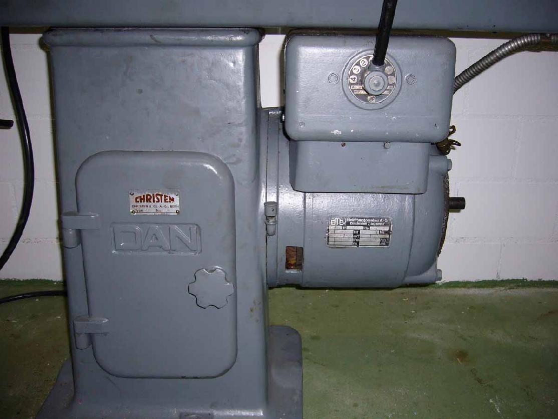
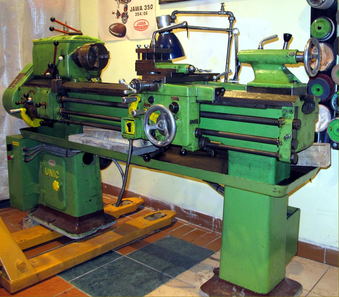
Built by one of the less-well-known Swiss makers, Christen & Company of Berne, DAN and UNIC lathes appear to have been made in a number of forms from the late 1920s until the 1950s - though when production ended is not known. However, Christen was a organisation better known in the 1950s and 1960s, for their Deckel-like precision universal milling machine and, in later years, for their beautiful drill and tool and cutter grinders.
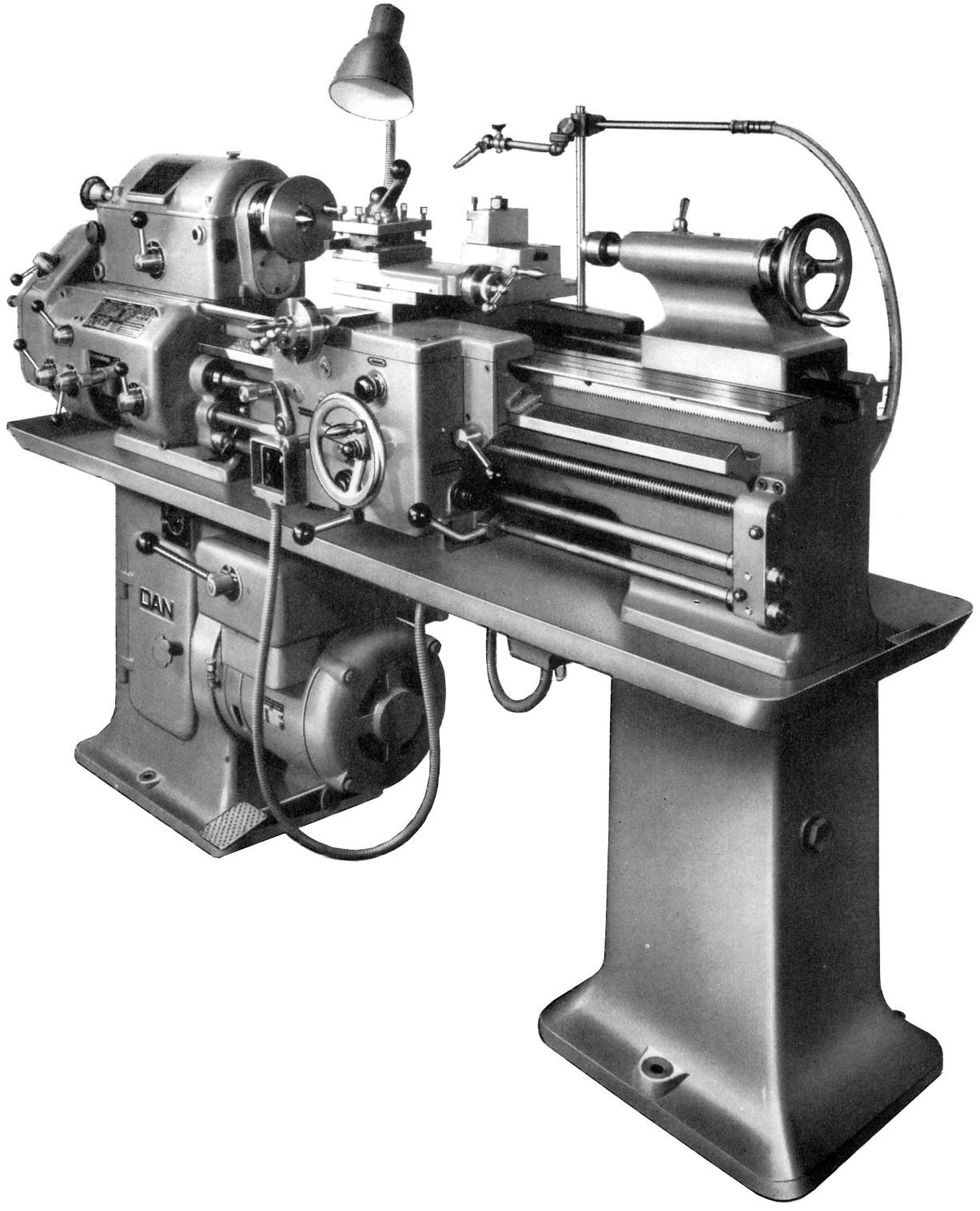
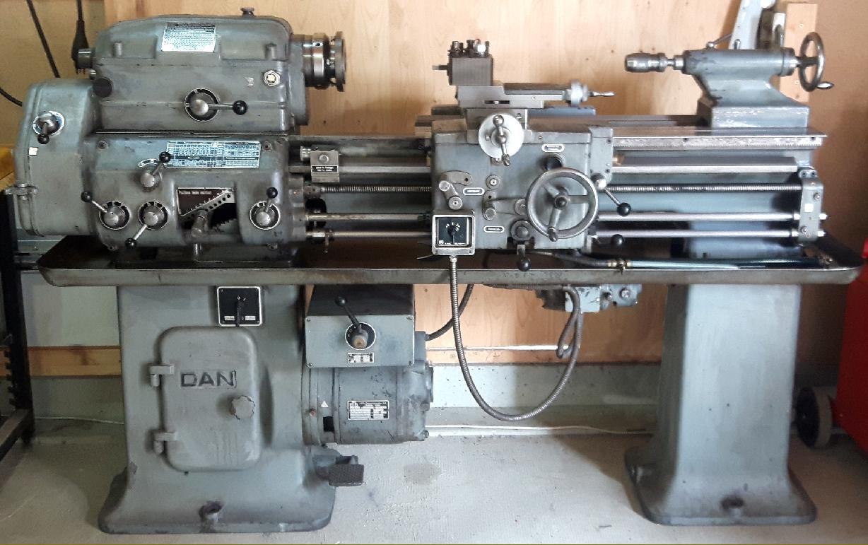
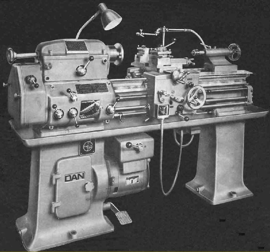
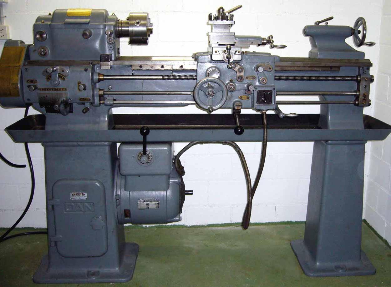
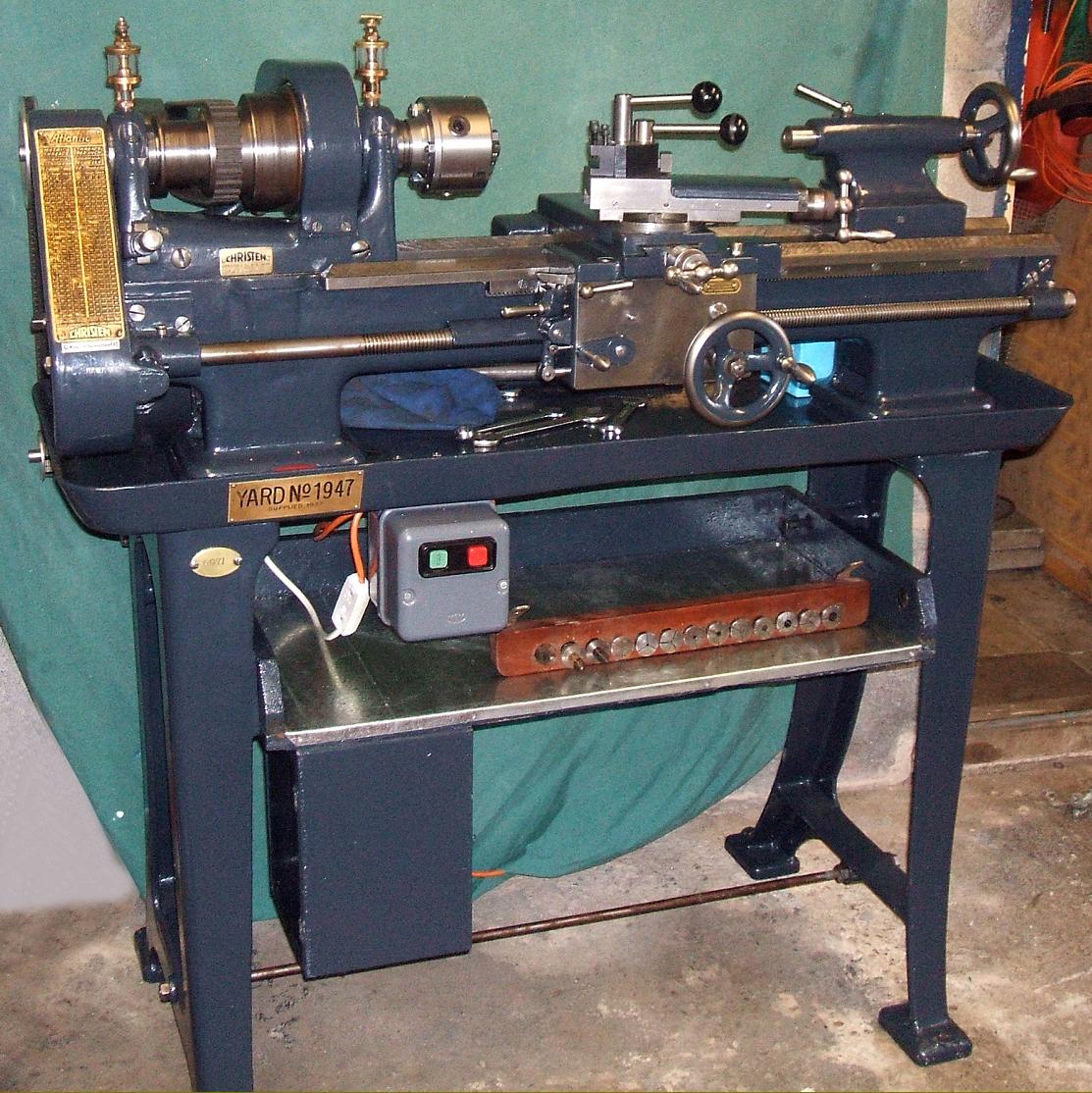
One example of the Christen lathe found more frequently than others is the DAN "Model 44", a 5.75" x 20" or 30" (145 mm x 500 mm or 750 mm) finely made precision-class machine with an excellent finish and fine detailing. Although introduced towards the end of World War Two, in 1944, the lathe was a development of a model first seen around 1929, a type known to have sometimes carried the branding "Atlantic" on its screwcutting chart. Like all Swiss machine-tools, this was both a thoroughly well-thought-out design and of exemplary quality and execution. Over a thousand examples of the earlier model were built but, at the moment, little is known of how well the "44" fared - however, from the writer's conversations with engineers trying to obtain deliveries of machine tools in the immediate post-war decade (with delivery times sometimes stretching beyond two years) there can be little doubt that it would have been a success.
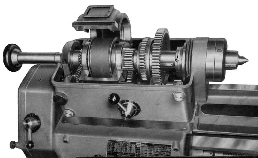
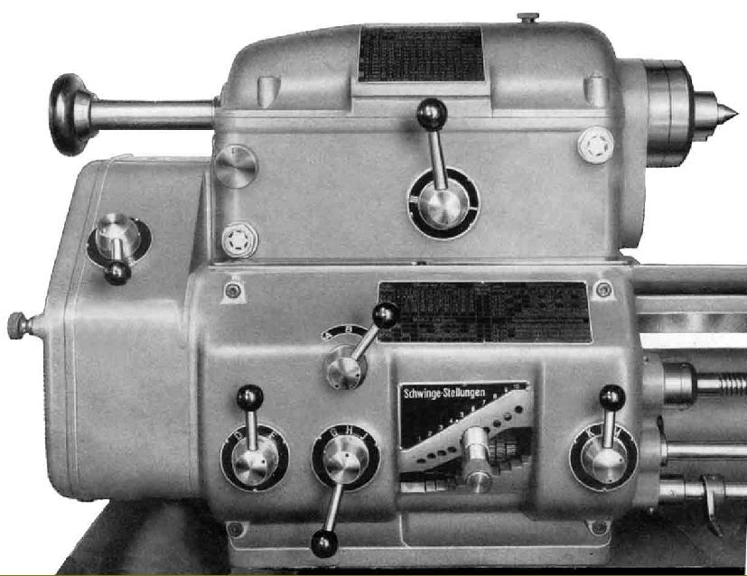
Of clean lines, the headstock carried a 7/8" (22 mm) bore spindle that ran in a long tapered bronze bearing at the chuck end and a pair of roller races at the rear - through which it was free to slide axially as it warmed up. To prevent the drive belt from transmitting vibrations into the spindle, or interfering with its accuracy, the single flat pulley spun in its own ball races with the drive taken through a peg and slot arrangement. The wide flat belt ran through a sealed compartment to prevent contamination from the oil-bath that lubricated a double-sliding, 3-speed gear arrangement that gave, when combined with a foot-braked 4-speed electric motor (mounted on an adjustable plate within the headstock cabinet leg), a total of 12 spindle speeds that spanned 45 to 1800 r.p.m. Unfortunately, instead of a simple threaded or industry-standard nose on the end of the spindle the makers chose to sacrifice both simplicity and owner convenience by using a design exclusive to themselves. The design consisted of a tapered section with a key, not dissimilar the American long-nose taper type - but with bolts instead of a screwed ring to secure chucks, faceplates and other attachments.
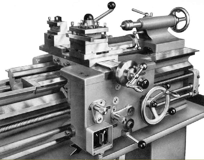
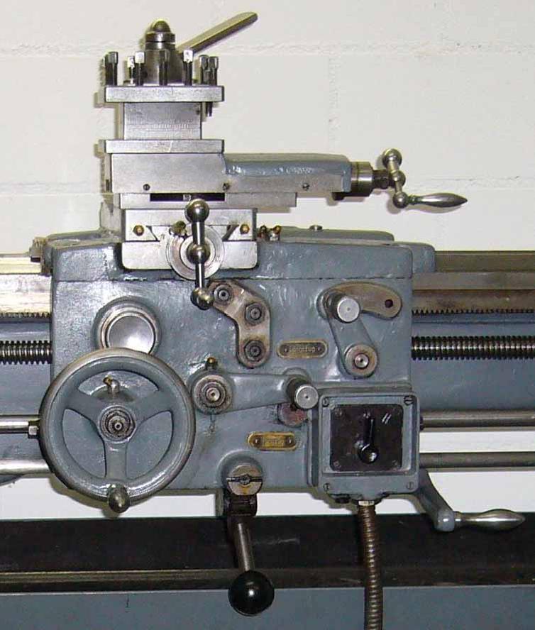
Looking particularly massive for so small a lathe, the unusual "double-height" box-ribbed bed sat on two cast-iron plinths with the right-hand unit housing the coolant tank and pump. The main carriage V-ways were set low down on the front and rear faces of the bed, with the tailstock running along a V and a flat formed on the top surface. Full-length covers were fitted over the ways that, while not completely effective, did afford some protection from chips and turnings falling on the finely-machined surfaces. Although the low-set, the carriageways ran right up to the headstock wth the bed's top surface stopping short of the headstock - and so allowing a usefully large gap to be formed without recourse to a removable section and its attendant deterioration in stiffness; this arrangement also had the advantage of ensuring that the carriage was always fully supported, even when right up against the faceplate. A particularly fine piece of work, the carriage was fitted with a deep, double-wall apron that allowed all gears to be mounted on shafts that were supported at both ends. Power sliding and surfacing was provided by a separate power shaft and engaged and disengaged by a vertical-action lever that protruded from the middle of the apron's lower edge; the design of the mechanism (like the similar system fitted to the Harrison L Series lathes) ensured that even under the heaviest of cuts the feeds could be flicked into and out of engagement with the lightest of touches. As a further aid to safety and operator confidence, an automatic trip was provided for the longitudinal feed that was adjustable, by a simple screw, to vary the disengagement point by as little 0.0004". Electrical control of the spindle was also centred on the apron, with a start-stop-forward-reverse lever pivoted from the right-hand wall and working through a long control rod; a master motor switch was also fitted on the front face of the headstock-end plinth. The rear of the cross slide was raised and provided with a T slot that could hold a rear toolpost (together with its raiser block) and also act as a mounting point for the extension necessary to couple with the (optional-extra) taper-turning unit. A 4-way indexing toolpost was fitted as standard and the compound slide micrometer dials were (especially for their era) of an unusually generous diameter; finished in satin chrome they were available with either metric or English graduations.
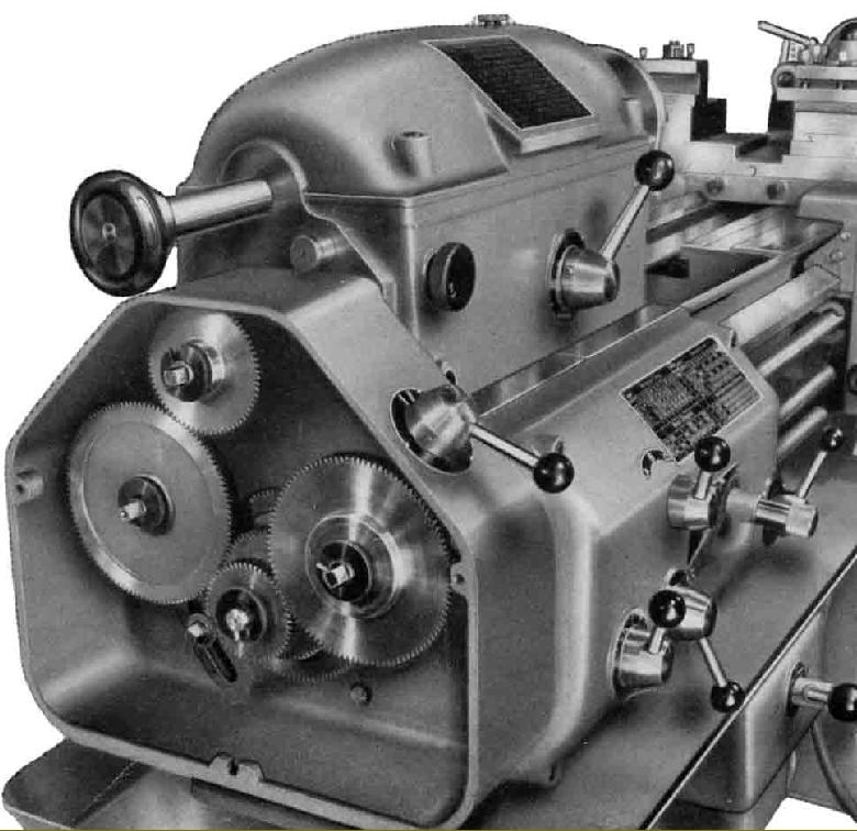
Divided into two sections, each with its own oil bath, the screwcutting gearbox held hardened gears and was driven through the usual train of changewheels from spur gears (in an oil bath) mounted inboard of the left-hand end of the spindle. Although the changewheels ran on studs from which they could be quickly detached (by the use of a simple slotted-washer arrangement) the gear-guard cover had to be unbolted and lifted off instead of hinging open. As standard, the box was able to generate 37 inch, 39 metric and 21 module pitches and was controlled through the usual method of a sliding tumbler combined with lever-operated rotary controls. Both the ground-finish, high precision, ball-bearing bushed leadscrew (and the power shaft) could be set to rotate in either direction (or be isolated) by a form of tumble reverse built into the headstock. 38 power sliding and surfacing feeds were provided that, for each revolution of the spindle, gave rates of 0.001" (0.0254 mm) to 0.04" (1.016 mm) and 0.0005" (0.0127 mm) to 0.02" (0.508 mm) respectively.
One version of the Dan lathe, the Type "750" (and possibly others), had a cleverly-engineered screwcutting arrangement similar to that on the Swiss Oerlikon where, when cutting a thread it was only necessary to disengage the drive at the end of the thread, while leaving the spindle running, return the carriage to the start point, and engage the clasp-nut lever, the lathe automatically finding the right engagement point.
Weighing approximately 1475 lbs (669 kg) the shorter-bed lathe was 66.5-inches (1689 mm) long while the other was 9.5-inches (241 mm) longer and tipped the scales at 1520 lbs. (689 kg).
If you have a Christen, Dan, Unic or "Atlantic" lathe (or any information about them) the writer would be interested to hear from you..