|
Some notes by the current owner:
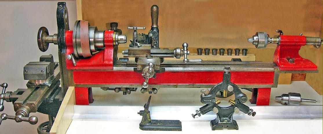
Manufactured by a little-known firm, the Cowan Engineering Co. Ltd. of Toronto, their 3.52 x 12" "bench precision" combination lathe and horizontal milling machine would have been constructed in the early years 20th Century. Similar in many respects to contemporary lathes of the same type from American makers such as Stark, Ames, Waltham Machine Works and Elgin, its origins were, at first, a puzzle. However the present owner was able to recall seeing, several years ago, a similar lathe bearing a "Cowan" logo and, sure enough upon stripping the lathe the maker's name emerged, together with some unintelligible characters, cast into the underside of the bed. Further research amongst his collection of the English Model Engineer magazine revealed an article in the November 4th edition of 1926 showed not just the same model, but the actual lathe itself. The pictures accompanying the text illustrated the workshops of one J .W. Evans, somewhere in Ontario, also included other Cowan products including drilling machines and three of the company's round-bed lathes. The combination lathe appears to have remained in the same area for its whole life, passing through several owners, including a retired machinist in Peterborough, Ontario, who had acquired it in 1973. until being purchased from him n February, 2008. Fortunately all or most of the original accessories had survived, together with a large collection of contemporary tooling (almost certainly from Evans) includes dozens of vintage Brown & Sharpe cast-steel saws, gear cutters, milling cutters and measuring instruments--all in excellent working condition. Evans had followed a career as a professional metallurgist and used his home workshop for experimental professional work, including smelting ores in small quantities using electrical apparatus of his own design and fabrication. He also authored four enlightening articles in Model Engineer with the first appearing on the 1st February 1906 and describing his early workshop and its electrical power supply - a commercial petrol engine driving two home-built A.C. dynamos constructed during the winter of 1905.
In the 24 August 1911 ME Evans describes building, in just 51 days, an impressive ½" scale working model electric smelting plant. This was able to produce, from crushed raw material, 7 lb bars of tool steel per hour. Material for a ½" by 6" steel cutter for his 8" centre height lathe was made in just two hours - from switching on the current to smelt the pelletised minerals. This model was eventually to be bought by the Geological Survey of Canada. Evidently a brilliant engineer - and with an uncommon ability to translate complex mechanical designs into actual machines quickly and using his own facilities - Evans' last article appeared in 1940 (when he must have been in his 70s or 80s) and described a model dynamo of advanced design.
Being very rare, Cowan bench lathes cannot have been produced in great numbers; indeed, having to complete with so many established makers, it is likely that only a handful were constructed. However, whilst competitors were producing bench lathes of comparable precision and size, few offered a horizontal milling attachment and of these the Cowan appears to have had the most robust and effective.
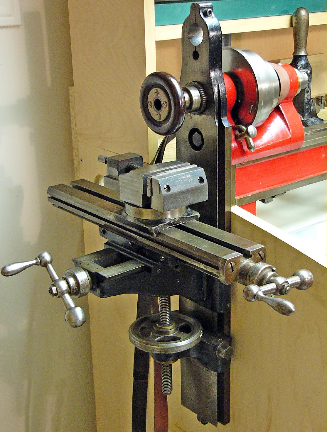
Milling details
Bolted to the headstock end of the Cowan's bed was a horizontal milling machine carried on a tall vertical cast-iron plate with its outer face machined with ways to take the knee. However, instead of being restricted to stub milling (as on many similar contemporary installations) the horizontal cutter arbor was properly supported by a 1-inch diameter over-arm - and this is also the only lathe known of its type and age that did not require the headstock to be reversed for milling. The over-arm passed through the top of the upright with its other end secured by a bracket bolted to the bed - rather in the manner of a massive fixed steady. Being relatively high (6") and long even with the over-arm in place a limited amount of work with the slide rest could still be accomplished. As a further benefit (and common with this type of combination machine) the milling table shared the same top profile as the lathe bed - so allowing the easy interchange of accessories. As a further bonus, if the slide-rest was fitted to the milling table very large diameters could be turned outboard of the spindle. With a travel of 15.75" longitudinally, 7" in traverse and 13" vertically the tables movements were particularly generous and allowed serious work to be undertaken--the machining of a 4-inch diameter gear or the mounting of a 5-inch diameter, ¼" wide side-and-face cutter on the arbor both being easily achieved. The owner reports that in practical use a half-inch wide cutter is the normal limit but, if care is taken, it will just about tolerate a ¾-inch (it even proved possible to take a delicate, 1-thou surfacing cut with a 11/2-inch diameter slabbing cutter some 2-1/2" long). Supplied with the table was a bolt-on, degree-graduated base that allowed the easy and rapid mounting of either a 31/16" capacity machine vice or a geared dividing head. The vice could be rotated through 180° and the dividing head 360° - with the graduations sufficiently well marked to allow easy and accurate setting by eye. The 80:1 worm-geared dividing head was particularly well constructed: it could be rotated in two planes, took headstock collets retained by a short drawbar, had a hardened and reversible dividing plate with different rings of holes on each face and the spindle locked rigidly with absolutely no backlash. In a recent test, using an early Brown and Sharp wheel cutter, a 33/8-inch diameter steel gear, 1/4" thick and with 100 teeth, was cut as an experiment. Set-up took 10 minutes and, with three rotations of the index plate (to cut the 16 DP teeth to depth), a machining time of 20 minutes - highly respectable for a one-off job.
Bed
Slotted down its centre line in the usual way to accept retention bolts for the headstock, slide rest and tailstock, the 26.75-inch long bed also carried a rear T-slot to mount a thread chasing attachment A useful addition, almost certainly offered as an accessory, was a 6-inch bed extension that allowed both a little extra capacity between centres and for the tailstock to be parked out of the way (instead of removed) when it might otherwise have interfered with the slide-rest. Planed, hand scraped and carefully fitted the extension was superbly made and set in perfect alignment by dowel-pins. Interestingly, once removed for cleaning, it was discovered that the bed extension could be bolted to the milling table and, when used in conjunction with the base of the machine vice, operated as a form of light vertical miller.
Two well proportioned T-rests, 4" and 6-3/4" long, were provided as standard.
Slide Rest
With covered lower, but exposed upper ways, the slide rest was of conventional construction with each slide having a useful 6 inches of travel, sufficient to cut the full length of a No. 2 or 3 Morse taper. Unless the result of an earlier owner's modification, the the single T-slot top slide had a right-hand ("cack-handed") feed screw thread, a counter-intuitive arrangement that produced a tool moment towards the work when the operator intended the opposite. "Balanced" handwheels were fitted together with neat, zeroing micrometer dials.
Tailstock
The tailstock barrel is 1-MT, self-ejecting type, with large zero-adjustable index graduated in 'thous'. The ¾" barrel travels 2" and is locked by opposing split collars. A long locking lever operates an eccentric against a shoe; push the lever forward and the tailstock locks solid. This is most convenient. Slight pressure on the lever locks the tailstock tight enough to drill steel with a 1/2" 1-MT twist drill. The tailstock does not set over for taper-turning. The long-travel, swivelling top-slide apparently made this unnecessary for most applications, and set-over has always been rare on precision bench lathes.
Specifications
Its previous owner, like Evans himself, called it a 3-1/2" lathe but it is really 3-3/8" centre height.
Headstock
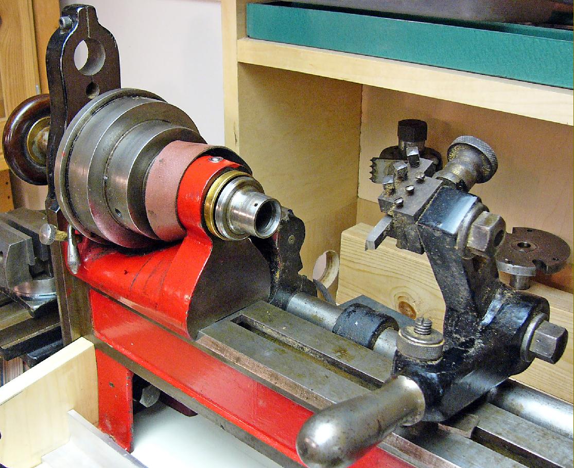
Of heavy construction the headstock casting carried a substantial spindle some 83/4" long bored ¾" clear. At the chuck end a traditional taper bronze bearing was used whilst at the milling-machine side a simple split-sleeve bearing sufficed - both lubricated though simple self-sealing spring-ball nipples. As both ends of the spindle were employed each was identical to the other and hardened - the drawbar being useable from either end..
The head bearing was not designed to take significant radial thrust because the milling attachment employs an arbor stabilised by an over-arm bar with centre.
The Cowan lathe mimics the BC Ames interpretation of taper nose fitting whereby workholding devices are pulled by the draw-bar against the tapered mandrel nose.
This centres and grips nose-mounted workholding devices quite well.
The ones which survive here are a 5" four-jaw universal chuck, a 6-1/4" faceplate, and a 3-1/4" catch-plate. These are prevented from rotating under load by a pin engaging in a longitudinal slot in the tapered nose. The only drawback seems to be that the fittings often must be knocked free using a brass bar through the spindle bore. The Hardinge system had a tapered nose but dispensed with the draw-bar. A characteristic Y-slot in the taper engaged against a pin in the fitting. This allowed twist-on, twist-off operation. This worked smoothly until the unhardened pin wore down, in which case the pin was simply replaced.
The headstock spindle pulley unit is intriguing to say the least. Oddly the back face has no index holes for locking the spindle when flats must be filed. Flats could actually be produced fairly quickly with the mill but a skilled worker could, given an indexable spindle, file a nice square or hexagon in a matter of minutes. Waltham produced a broadly similar lathe with planetary reduction gearing contained within the headstock pulley. Evidently the pulley of the Cowan lathe has this feature too - it contains some sort of mechanism - but it is stuck in the locked setting and defies attempts at disassembly. The owner has reconditioned dozens of lathes so this resistance to disassembly is most perplexing. It is hypothesised that back-gearing is engaged by pulling out a knob on the pulley's rear face. This has somehow been jammed stuck. A shoe connected to the cranked lever, at the rear of the headstock, is apparently meant to press this knob inwards, presumably the direct drive position. The shoe when rotated forward also engages between two protruding pins meant to lock the spindle for removing chucks.
The headstock and dividing head accommodate through-bored, draw-in collets of Hardinge style but not manufacture. These collets are 2-11/16" long and 1" maximum diameter over the cone. The threaded portion is 5/8" long with a 24 TPI 60° fine slightly tapered thread 21/32" diameter at commencement. They are hardened and ground but not marked with any maker's name. They are probably Canadian in origin because the thread angle is 55° and British measures were standard in Canada. There is no reason to think Cowan made them because most lathe makers got their collets from speciality firms.
Drive System
The lathe is designed to be driven from a pulley on a shaft above. This is a mirror image of the headstock pulley with one-inch convex belt surfaces 4-1/2", 3-1/4", and 2-1/4" diameter. It has a leather-faced clutch operated by a long iron lever. The clutch is well designed. It is quick, positive, and vibration free.
|
|