|
Continued:
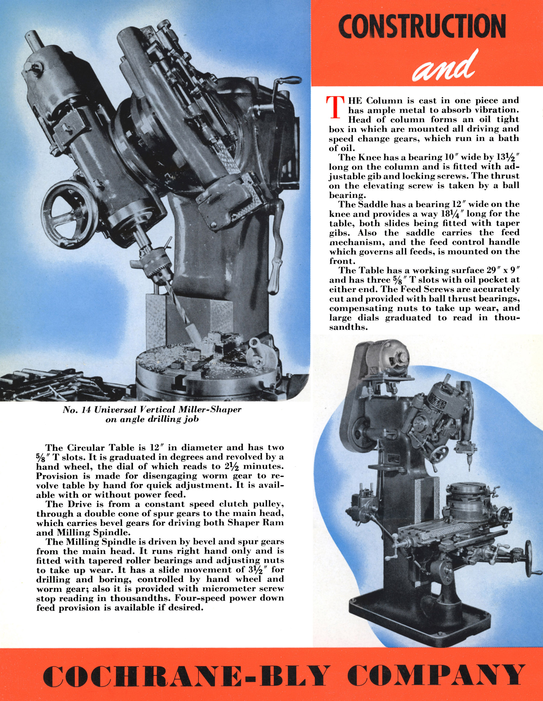
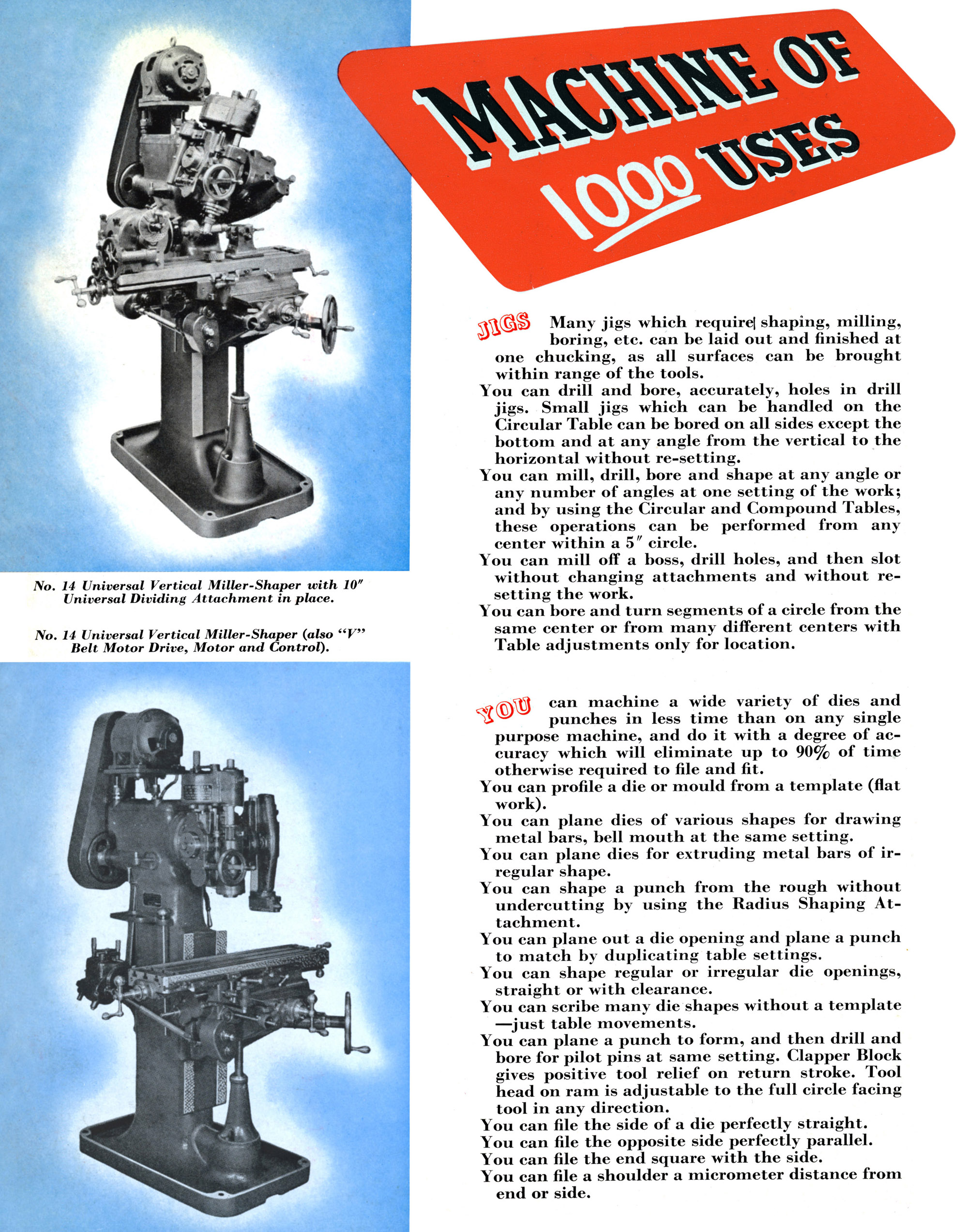
Both heads were carried on a common, swivelling boss that protruded from the front face of the speed-change gearbox and secured by three bolts running in a circular T-slot. The arrangement allowed a rotation of a full 360°, the setting being made easier by the provision of crank-handle operated, worm-and-wheel gearing. In addition, each head could be swivelled, independently, at right angles to the axis of the horizontal support. There was a slight difference in the amount of swivel available for each head: that for milling being inclinable to 45° each side of "vertical" while the slotter was limited to 40°. All rotational elements had degree scales engraved around their circumference with, at extra cost, the provision of vernier markings. The maximum clearance between the end of the milling heads spindle and table was a useful 20 inches and 18 inches for the slotting head.
From the motor or countershaft drive - using a wide flat belt - the drive passed to the gearbox input pulley, this running on roller bearings and incorporating a clutch, the operating handle for which was pivoted from the column's right-hand face. The gearbox was a simple type with a cone of five hardened gears carried on a slotted shaft, the speed required being engaged by a sliding key. On early machines a tumbler-style reversing gear was built into the milling head but, as the top speed was rather low - perhaps around 330 r.p.m. - later versions did away with this and were fitted instead with an auxiliary gearbox on top of the milling head that doubled the number of spindle speeds to ten - these now being a much more useful 55 to 2122 r.p.m. Speeds were selected by a long quadrant lever pivoting from the right-hand face of the column, the side of its arc being engraved with the five stroke rates - these ranging from 25 to 150 per minute. As time passed, although the main column and gearboxes appeared to remain the same, a number of other modifications and improvements were made including the mass and size of tables and the option of a Pratt & Whitney precision measuring system.
Driven by spur and bevel gears, the vertical head contained a B & S No. 9 taper spindle that, on early versions ran in tapered bronze bushes fitted with adjuster collars and, on later machines (from an unknown date), in either adjustable taper-roller bearings or possibly ball races. The 3.5" of quill travel was under the control of a fine-feed handwheel working through worm-and-wheel gearing - a micrometer screw stop was also fitted, its dial graduated in thousandths of an inch. Power down feed was an optional extra, the four rates of feed spanning 0.0004" to 0.026" per revolution of the spindle.
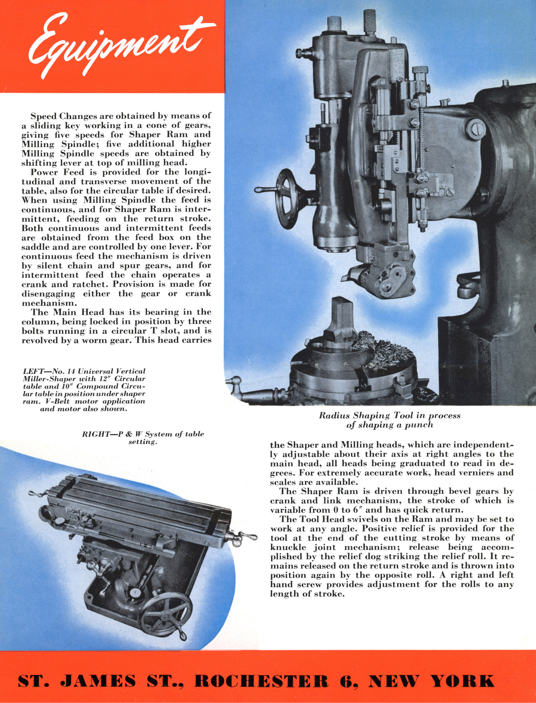
Also driven by spur and bevel gears, the slotter ram was oscillated by a crank and link mechanism, had a stroke variable between 0 and 6 inches and incorporated a quick-return mechanism. The toolholder could be swivelled on the end of the ram and so set to work at any angle - a positive relief being provided at the end of the cutting stroke by a knuckle-joint mechanism with release by a "relief dog" striking a "relief roll". The tool remained free on the return stroke until engaged again for the cutting stroke by an opposite roll. The rolls had to be set correctly as the length of the stroke varied, this being achieved by a left and right-hand threaded screw-adjuster fitted with a knurled head for an easy grip by oily fingers.
Fitted with three 5/8" T-slots, the table had a working surface of 29" x 9" with coolant troughs at each end. Both table feed screws ran through bronze nuts, adjustable to eliminate backlash and provided with ball thrust races for an improved feel. Longitudinal travel was 18.5 inches, in traverse 9 inches and 18 inches vertically - the lifting screw being equipped with a ball-thrust race and (on early examples only) so long that a hole needed drilling in the floor to accommodate it. Drive to the table came from a gearbox mounted to the rear of the left-hand face of the column, the connection to the table selector gearbox being by the usual universally-joined and splined shaft that allowed for knee elevation. For milling work the drive was, of course, continuous and driven by a combination of "silent chain" and spur gears. However, for slotting and shaping the drive needed to be intermittent, acting between the cutting strokes, this motion being obtained by the chain operating a crank and ratchet mechanism - just like the box-table drive seen on traditional ram-head shapers. Control of the table-feed setting was by a two-position selector lever at the back of the column marked "Mill" and "Shaper"; when the latter setting was engaged, the table feed and ram were timed together to prevent the table moving during the cutting stroke. For a machine concerned with high-precision work, some might have thought the diameter of the table feed-screw micrometer dials to be rather modest - though as compensation it was possible to mount a Pratt & Whitney system of precision length rods and dial-test indicators on each axis, the easily-damaged dials being protected by hinged covers.
One very useful attachment offered by the makers -and essential for using small-diameter cutters, was a simple subsidiary high-speed attachment that slotted into the main spindle and drove, by step-up gears , a second parallel spindle (with a Brown & Sharpe No. 4 taper) that ran four times as fast. Also available was a 12-inch diameter rotary table - this being fitted for either hand or power drive - and, to mount on it, a second, 10-inch table carried on a screw-feed slide. This double assembly, a "universal protractor" allowed work to be marked out and machined from any centre within a 10-inch circle - so opening up a further variety of machining operations. Other items listed included the expected direct-fitting collets for the spindle; spindle draw bars; a drill chuck; machine vices; expanding milling arbors; a tapered centre for the rotary table and a self-contained motor drive..
|
|