|
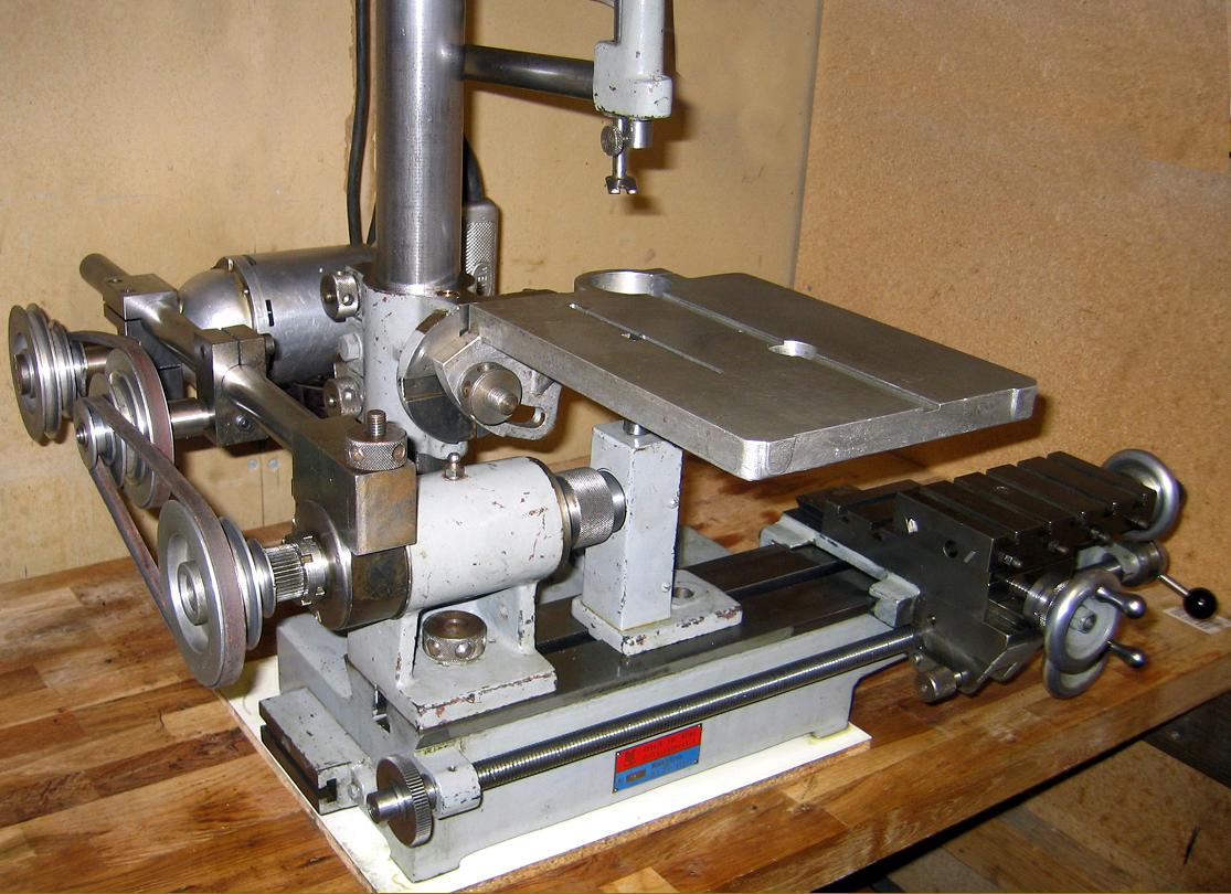
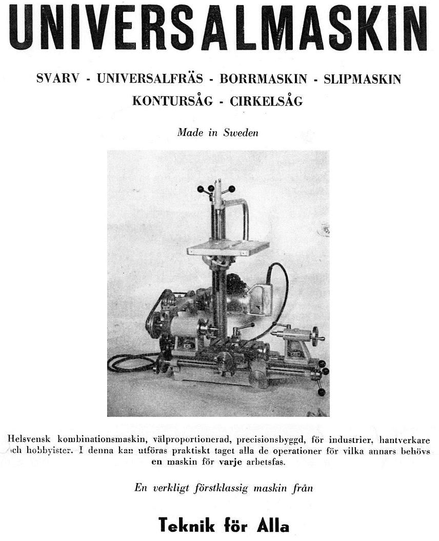
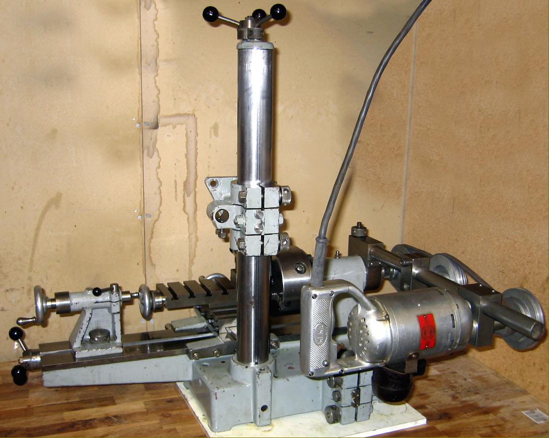
Built in Sweden by R.L Carlstedt, the Teknik for Allas (Techno for Everyone) was an ingenious assembly of parts that allowed for turning, screwcutting, vertical and horizontal milling and jig-sawing. Beautifully constructed, with an excellent cosmetic finish and fine detailing, it followed the basic design concept of the better-known German Hommel UWE and, to some extent, that of the original Unimat. Weighing a not inconsiderable 80 kg, the 88 mm centre height by 380 mm between centres Carlstedt used the bed of a conventional small lathe with a flat top, 60-degree V-edge ways and a carriage that was left permanently in place.
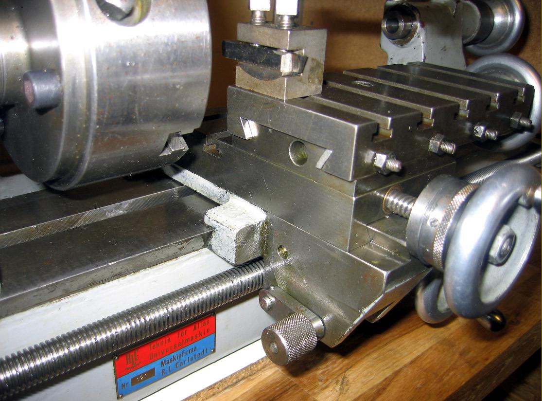
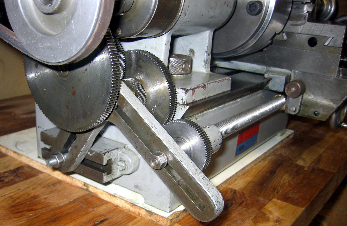
The bed was extended both well backwards and towards the No. 1 Morse taper tailstock to provide a choice of two sockets (spaced left to right) into which could be fitted a 55 mm diameter vertical column to carry the demountable headstock and its drive. The hole to the left was keyed to keep the head aligned with the bed, the one to the right was bored plain and without any apparent means of locking the post in place. An ordinary leadscrew was fitted, with screwcutting arranged by bolting a T-slotted bracket to the headstock-end of the bed and securing to it, and to an extension on the left-hand face of the leadscrew bearing bracket, a right-angle arm to carry the changewheel studs. The set of gears provided (32, 36, 40, 42, 50, 60, 80, 100 and 127t ) allowed the generation of both metric and inch pitches.
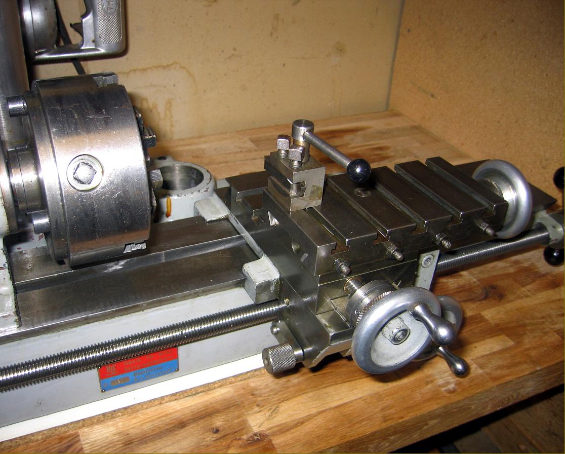
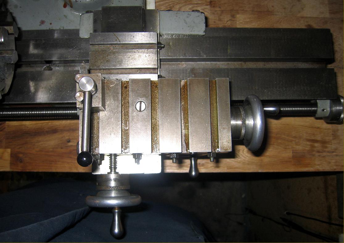
Of decent specification, the compound-slide assembly had a cross-slide with two T-slots, 75 mm of travel and a 80 x160 mm top slide with five T-slots, 100 mm of travel and able to be swung 60° each side of central. Of relatively large diameter, both feed screws ran through replaceable bronze nuts, were fitted with proper, full-circle handwheels and equipped with good-sized, zeroing micrometer dials. On the apron, a single-sided nut could be raised and lowered to engage the leadscrew drive with a quick-feed handwheel the gear attached to which drove not to a bed-mounted rack, but direct onto the leadscrew, a system also used on the Myford ML10. Like the latter, the latter arrangement was poor, with the motion "cack-handed" (i.e. a turn of the wheel to the left to advance the carriage instead moved it to the right) and the gearing far too high. At the tailstock end of the leadscrew was a capstan handle fitted a micrometer dial. Unfortunately the arrangement was poor with the small handle being awkward to grip.
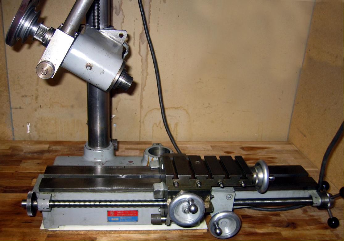
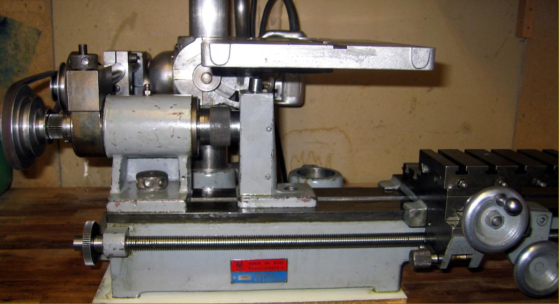
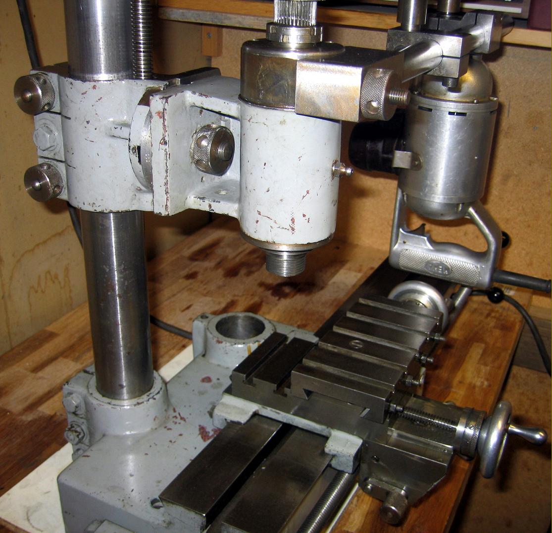
Oddly (though perhaps conveniently), the headstock spindle had a standard Myford Series 7 nose (1.125" x 12 t.p.i.), a 15 mm-bore and a No. 2 Morse taper. As the headstock was intended to be removed and repositioned, the arrangement of its countershaft system required some careful thought. The answer was to employ a large commercial hand drill (in the manner also used by the Swiss-built Astoba) with the whole assembly carried on a steel bar fitted with a 2-stage, A-section V-pulley drive that gave speeds of 135, 300, 1700, and 2780 r.p.m. The drill was rather special, being very robust and well made and fitted with a large (brown plastic) bolt-on reversing switch; unfortunately the unit was noisy, and howled like a small vacuum cleaner with a metallic gear rumble overtone….
In order to allow the countershaft to be detached quickly, it was fastened to the headstock by a steel band that tightened around a turned surface, a knurled-edged nut with Tommy-bar holes being used to tighten the assembly (fastenings of an identical type also being used on the Astoba). When mounted in the vertical position the headstock was carried on a casting that allowed it to be swivelled and also driven up and down the column under the control of a feed screw topped by a small capstan handwheel.
Of simple design, the No. 1 Morse taper tailstock could not be set over for taper turning and was secured to the bed by an inconveniently positioned Tommy-bar nut hidden in a recess at the back; to compound the misery, the spindle was locked by that horrid means of a slot in the casting tightened down by a bolt.
Supplied with each new machine were: a vertical slide, a mounting column, a toolpost, 8 changewheels, a catchplate, faceplate and polishing plate, 2 Morse centers, a "graduated" plate for the vertical slide, 5 hexagon keys, 2 locking handles, a "polishing table", a spindle on which to mount a circular saw, a CEJ boring-chuck and a number of other small fittings and mounts.
Overall dimensions of the Carlstedt Universal machine Tool were: 800 mm long, 440 mm wide by 670 mm high.
|
|