|
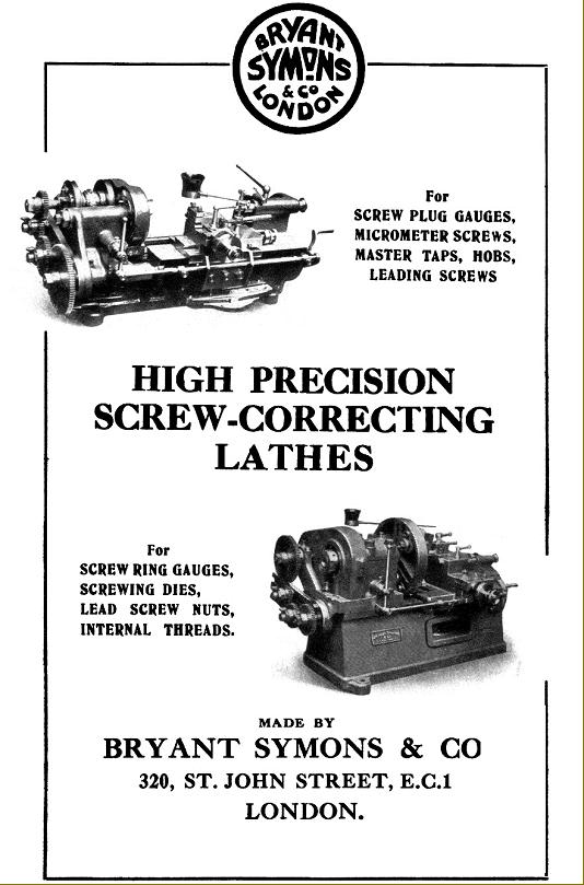
Founded in 1901, the original interest of the Bryant Symons Company was in the development and manufacture of precision ruling and engraving machines (mirroring, to some extent, the work being done at the time in Switzerland by SIP) this leading to the production of machines for making high-precision leadscrews and the pitch correction of threads. Further expansion resulted in work connected to very high-quality optical work and by 1930 the original factory had been outgrown and a move was made from the original premises at 320 St. John Street, London, E.C.1 to a new factory at Tottenham, where they remain to this day. Recent products include a number of ultra high-precision diamond-turning and facing lathes able to produce a surface finish better than 0.01 microns with a roundness better than 0.10 microns and flatness on facing operations exceeding an accuracy of 0.10 microns.
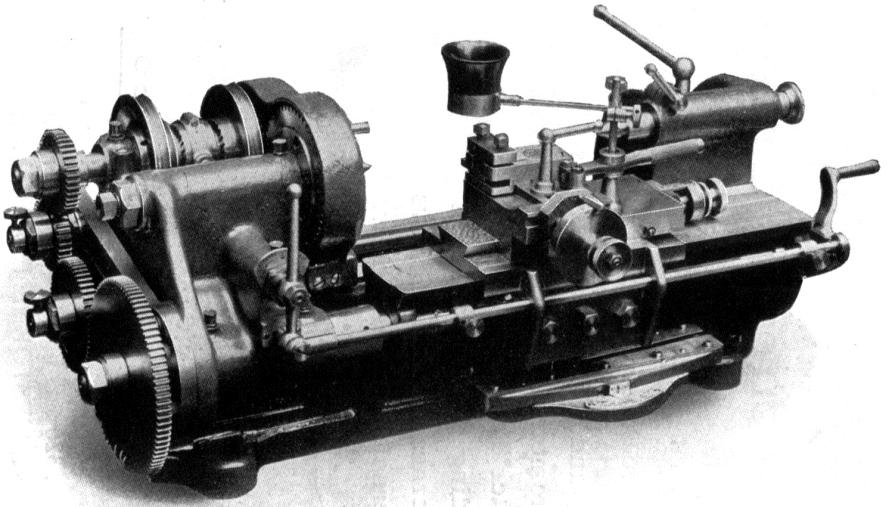
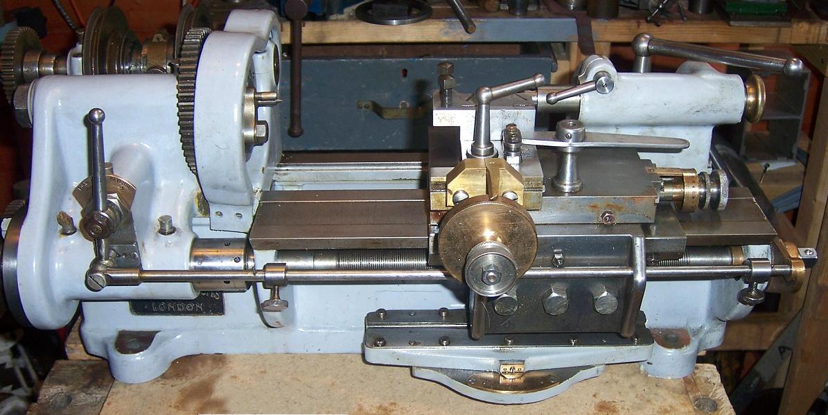
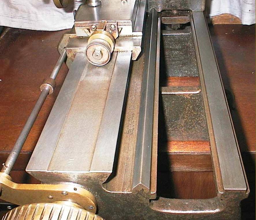
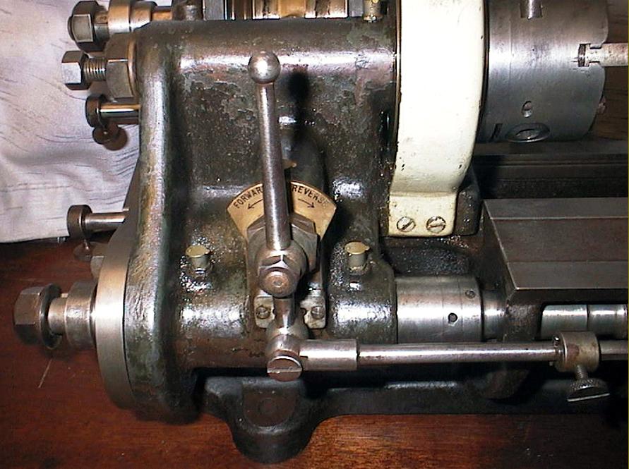
Manufactured when they were at their London address, the ingenious and beautifully made little Bryant Symons lathe shown below was designed for the correction, checking and measuring of very high quality screws, thread gauges and taps, etc. With a centre height of 2-inches, and 8 inches between centres, it was fitted with a clever leadscrew pitch-correcting device patented by Mr. A. B. Symons in 1917 - each example of the lathe being supplied with a certificate of accuracy from the National Physical Laboratory. The lathe's intended function was identical to the similar (though different in detail) Swiss-made machines by SIP (Société Genevoise d'Instruments de Physique) - also made during the 1920s. The Bryant Symons was an expensive proposition, one supplied in 1941 being found intact with the original invoice for over £500 - the price, at the time, of a decent house.
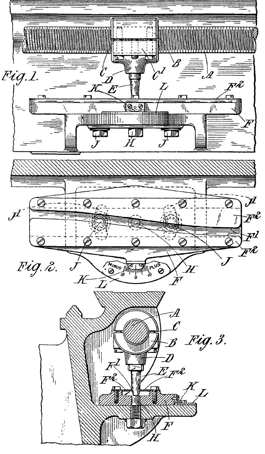
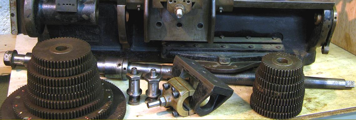
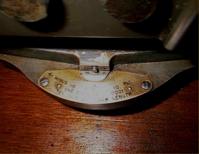
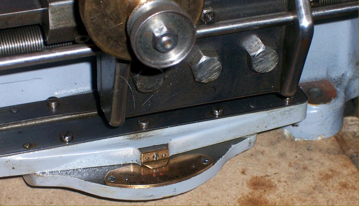
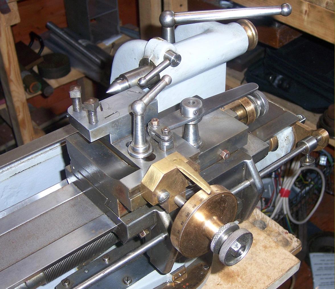
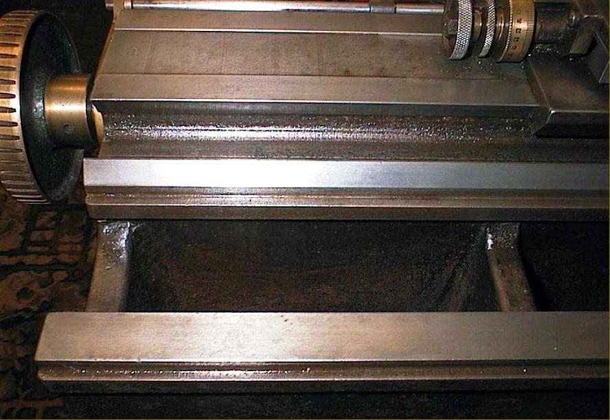
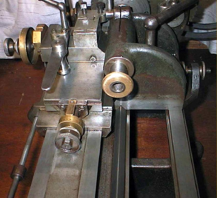
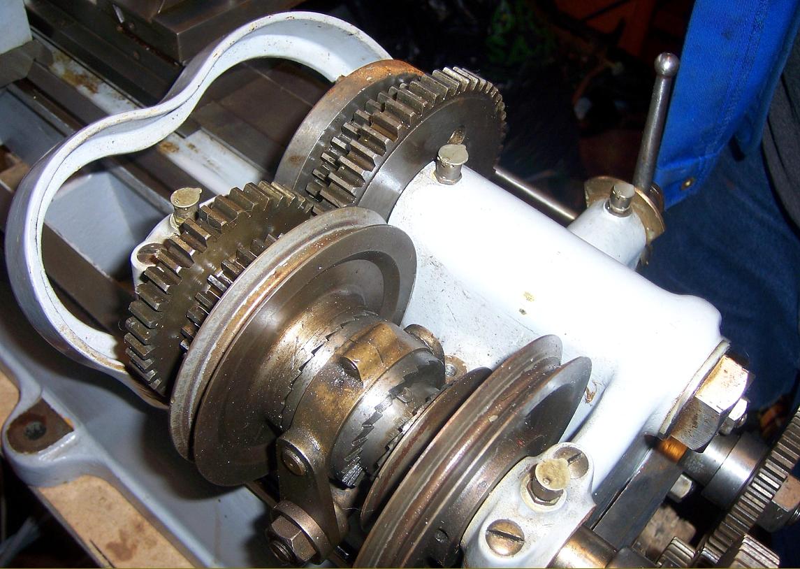
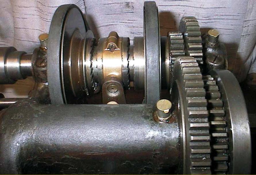
As only the American Moore Company was (eventually) able to achieve on a commercial basis (though on screws limited to 20-inches long) an absolutely dead accurate leadscrew with no variation of pitch from end to end that generated precisely the same linear movement throughout its range, screws of lesser accuracy required some means of correction. To engineer this, Symons arranged for the leadscrew (which was made to very tight tolerances) to be of large diameter, made from hardened Bessemer steel and cut with a 30-degree V-thread at (a very fine) 16 threads per inch. Unlike the SIP lathes, which carried their leadscrew in the best theoretical position, down the centre line of the bed and protected beneath it, that on the Symons was at the front, through supported in a long bearing at its left-hand end with special care being taken to face the flanges dead flat to stop the screw being oscillated from end-to-end. An adjustable phosphor bronze clasp-nut was fitted into a carrier mounted on the saddle and, while held rigidly in a longitudinal direction, was able to correct pitch errors by being allowed to moved very slightly in a rotary direction from either side of central. The fractional turn of the nut was arranged automatically, by a steel rod attached to it and projecting downwards to engage its tapered end in a slot formed as a gentle wave by the edge faces of two thin steel plates bolted to a carrier beneath the leadscrew. The wavy slot (the same length as the leadscrew's threaded section) caused the rod to be moved backwards and forwards and so impart a very slight turning motion to the clasp nuts. The unit supporting the slot plates was able to be swivelled about its centre point and the amount of correction altered, the aim being to obtain a uniform increase or decrease in pitch to compensate for changes caused when a workpiece was, for example, hardened. A scale was attached to the front of the unit with degree marks indicating the plus and minus correction that could be obtained.
Continued below:
|
|