 |
|
|
|
|
|
|
|
|
|
|
|
|
|
|
|
|
|
|
|
|
|
|
|
|
|
|
|
|
|
|
|
|
|
|
|
|
|
|
|
|
|
|
|
|
|
|
|
|
|
|
|
|
|
|
|
|
|
|
|
|
|
|
|
|
|
|
|
|
|
|
|
|
|
|
|
|
email: tony@lathes.co.uk
Home Machine Tool Archive Machine-tools for Sale & Wanted
Machine Tool Manuals Machine Tool Catalogues Belts
Books Accessories
Late-type
Boxford Industrial & Training Lathes
289, 280T, STS 10.20, TS 10.20, TF 10.20, TH 10.20, 330TR, TR.11.30, 330, 280, 280T, 330IS, 280IS, 250IS, 11.30, 11.20, 10.30 and 10.20
An Operation, Maintenance and
Parts Manual is available for these lathes.
|
|
|
|
|
|
|
|
|
|
|
|
|
|
|
|
|
Overlapping the slow demise of the original "belt-drive" lathes that had been the mainstay of the Company from the late 1940s, by the early 1980s Boxford's lathe range spanned a selection of surviving older types (AUD, BUD, CUD, TUD and ME10), a number of CNC training lathes (designed expressly for use in schools and colleges) and a new geared-head model of conventional design also sold in the United States and Canada branded as a "Clausing". Like the original "belt-drive" types, the new lathe was based on a single basic model but with a large number of interchangeable parts and offered in a wide - indeed, rather bewildering - range of configurations. The range was split into three groups: training lathes listed as the 289, 280T, STS 10.20, TS 10.20, TF 10.20, TH 10.20; toolroom-class machines as the 330TR and TR.11.30 and the industrial types (some of which were, confusingly, also listed in the training category) as the 330, 280, 280T, 330IS, 280IS, 250IS, 11.30, 11.20, 10.30 and 10.20
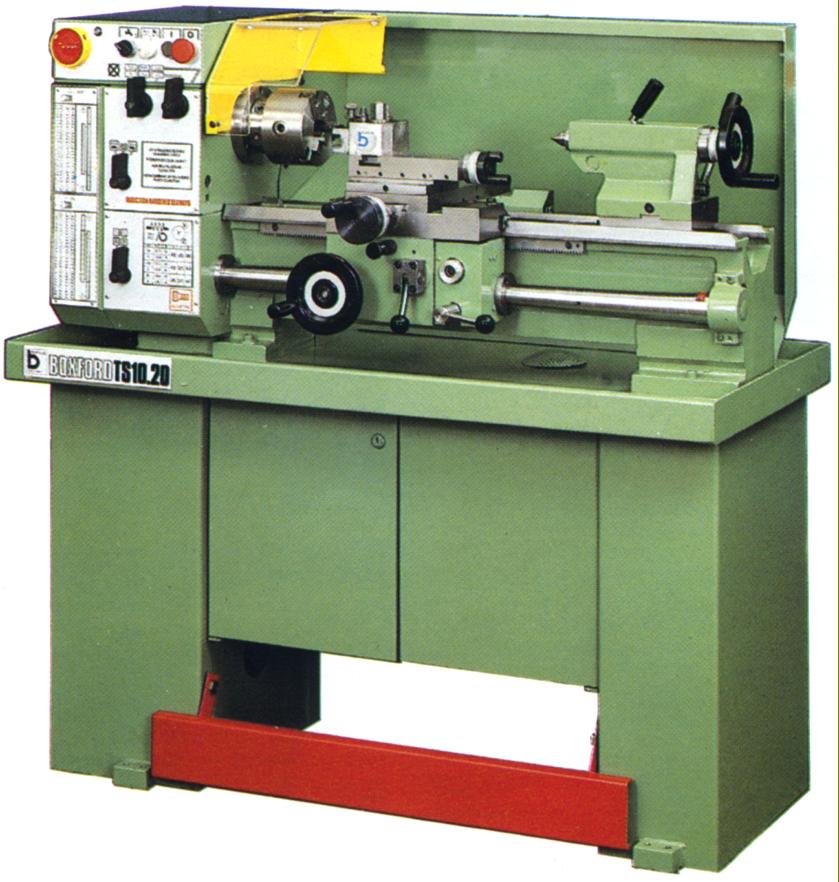
As the lathes all shared the same bed and carriage assembly, if the maker's Model sticker is missing, an estimation of the centre height can be made by looking at the block between top and cross slide: on the larger lathes this is of considerable thickness--but on the smaller versions rather thin. Models with screwcutting gearboxes can be recognised by a row of three levers in line with the leadscrew while lathes with changewheels for screwcutting have only one.
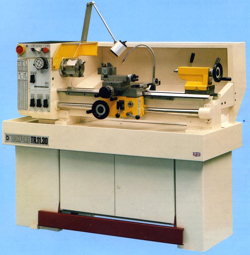
TR 11.30 Toolroom
Introduced in May, 1982, at £3500 and built to achieve various international accuracy standards, the makers claimed that the 140 mm (5.72") centre height "TR.11.30 Toolroom" qualified for the very high ISO:1708-1979 and BS-4656 specifications, while also conforming to DIN8606 for lathes of high accuracy, ASA.BS.16 Toolroom Lathes and the G.Schlesinger (1978) Table 13 Toolroom Standard.
Admitting a useful 750 mm (30") between centres, the TR.11.30 had a heavy and rigid bed (induction hardened and ground as standard) 190 mm (7.5") wide with V and flat ways. As on all versions of these lathes, the rear bed V-way was cut away under the spindle for a length of 150 mm (6") to give a slightly increased swing. The machine was carried on a robust cabinet stand with a lockable storage cupboard and a full-length splashback that incorporated a tool tray.
With a 35 mm (1.375") bore, a hardened D1-3" nose fitted with a No.4.5 ASA.B5.10 bush machined down, internally, to a No. 3 Morse taper, the spindle ran in expensive bearings by either Gamet or Timken of the Ultra Precision type. Driven by a 1.5 kW (2 h.p.) motor fastened to an adjustable plate behind and below the headstock, the nine spindle speeds spanned a useful 54 to 3000 r.p.m. - with a powerful, electrically operated spindle brake fitted as part of the ordinary specification. The well-supported spindle, together with the splash lubricated, hardened and ground headstock gears (that had been finished on state-of-the-art Reishaur machines), ensured that the lathe made little noise - the maximum level being some 83 Dba. Spindle-speed control (as on all the industrial models) was by a pair of concentrically-mounted dials of the safety-type that had to be pushed and turned to operate.
All within easy reach, the electrical controls were clustered across the top of the headstock's front face and included an emergency stop button and an isolator switch that could be padlocked. Safety micro-switches that cut the main motor were fitted to the chuck guard and changewheel cover, while a full-length safety kick stop was available, at extra cost, to fit across the front of the stand at floor level.
Running in sealed-for-life ball races, the 25 mm (1") diameter telescopic spring-cover guarded leadscrew could be had with either a 6 mm or 4 t.p.i. pitch. It was driven by a fully enclosed, all-lever-operated, dual English/Metric screwcutting and feeds gearbox that provided 39 metric threads from 0.2 to 7 mm and 34 English from 3.5 to 80 t.p.i. By substituting four changewheels BA pitches from 0 to 8 BA could be generated and, with two additional changewheels and an auxiliary mounting stud, twelve Module pitches from 0.3 to 2 MOD together with 24 Diametral (DP) from 14 to 60 DP. A thread-dial-thread indicator was built into the front face of the apron. As a point of interest, the screwcutting and feeds gearbox and apron were both packed from new with Shell Alvainia R1 grease - or its equivalent - and under normal working conditions should not require any further lubrication.
The standard colour was, perhaps, rather unusual, being white with a yellow tailstock and apron; for the more conservative mined buyer the TR.11.30 could also be had, at no extra cost, in RAL Green (6011).
Continued below:
|
|
|
|
|
|
|
|
|
|
|
|
|
|
 |
|
|
|
|
|
|
TR 11.30 Toolroom Lathe
Continued:
Twelve rates of sliding and surfacing feeds were provided, the former from 0.12 mm (0.0005") to 0.6 mm (0.024") per rev and the latter at exactly half that rate.
Completely sealed and with the internals running in an oil bath, the apron had controls consisting of a carriage handwheel with micrometer dial, a simple push/pull button to select the power feed direction and a lift-and-lower lever to engage the feeds - the drive passing through an adjustable, apron-mounted torque-limiting clutch, with further protection provided by a brass shear pin in the changewheel drive.
Fitted with a full-length cross slide 140 mm (5.5") wide with 175 mm (6.875") of travel, the compound slide rest was heavily built, with locks on both slides (one of the central gib adjustment screws being adapted for the purpose) and fitted with crisply engraved, satin-chrome-finished zeroing micrometer dials - that on the cross slide being of a usefully large diameter and easy to read (the divisions giving a direct reading of the reduction in diameter). The T-slotted top slide could be rotated through 360°, had a travel of 3.75 inches and was equipped with a Dickson quick-set toolpost - an ideal fitting on this class of machine. As befitted a machine of this type, both slides had closely-spaced gib-strip adjustment screws of the self-locking type,
Travel of the set-over tailstock's large diameter (37 mm (1.47") No. 3 Morse taper spindle was 95 mm (3.75") with a dual-reading inch/metric micrometer dial to help gauge the setting. A powerful, split-barrel from of spindle lock was fitted, operated by a usefully long handle.
A wide range of accessories was offered including some, such as Low-voltage halogen lighting and coolant that should have been fitted as standard. Other items listed were: taper turning; high-speed threading; hydraulic copying; digital readouts of carriage and cross-slide travels; rear-mounted motorised milling and drilling attachments; 6-station bed-mounted capstan unit; toolpost grinder; pneumatic chucks; super-precision direct-mounting 3-jaw chucks; an 11-inch faceplate; 48-position indexing 4-way toolpost; a simple single block toolpost able to take a single tool up to 12 mm (0.5") square; rear toolpost and accessories; milling, dividing and gear-cutting attachments (using cutters mounted in the chuck); fixed and travelling steadies; plain and micrometer carriage stops; cross slide stops and a T-slotted boring table.
Continued below:
|
|
|
|
|
|
|
|
|
|
|
|
|
|
 |
|
|
|
|
|
|
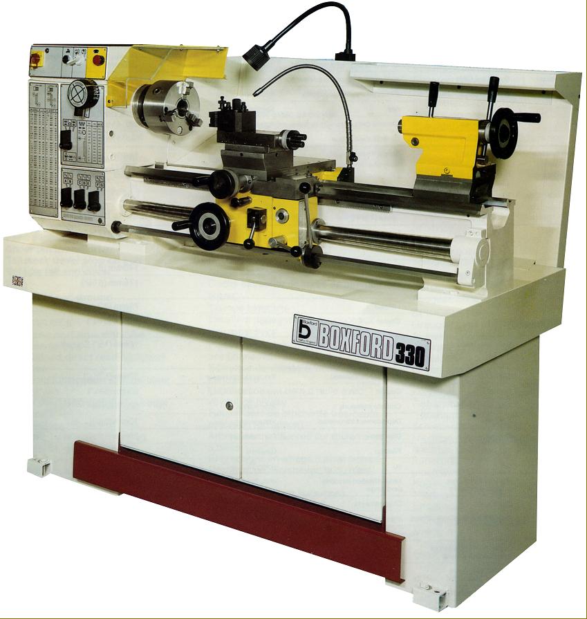
Boxford 330IS--also built as the 280IS and 250IS
Continued:
Boxford "IS" Industrial Lathes
Built as the 330IS, 280IS and 250IS (the numbers indicating the swing in mm, respectively 13", 11" and 10") the IS range of lathes was introduced during 1964 at prices of, respectively, £3650, £2725 and £2675. Apart from the centre height, the only differences between the models was the motor type and speed range, the 330IS having a wide range of options (detailed below) while the other two were each fitted with a 1.1 kW (1.5 h.p.) motor that gave 9 speeds from 40 to 2240 r.p.m.
Early IS machines were finished in RAL Green (6011), then in a two-tone white and yellow (though the green remained a no-cost option for the conservative buyer) and finally in a two-tone light and dark green. Two between-centres' capacities were available: 750 and 1000 mm (30" and 40"). Sharing a large number of parts with other models in the range, they were closest in specification to the TR.11.30 Toolroom, but built to normal standard of accuracy - though they were also available, at extra cost, constructed to a higher-ISO 1708 DIN 8605 toolroom specification, the specification including super-precision headstock bearings.
Heavy and rigid, the bed was induction hardened and ground, 190 mm (7.5") wide and with V and flat ways; as on all versions of these more modern Boxford lathes, the rear bed V-way was cut away under the spindle for a length of 150 mm (6") to give a slightly increased swing. The machine was carried on a robust cabinet stand with a lockable storage cupboard and full-length splashback that incorporated a tool tray positioned towards the tailstock end.
With a 35 mm (1.375") bore and a hardened D1-3" nose fitted with a No.4.5 ASA.B5.10 bush (machined down, internally, to a No. 3 Morse taper), the spindle ran in Timken taper-roller bearings. Fastened to an adjustable plate behind and below the headstock, on the 330 IS only, a number of motors (and speed ranges) could be specified that allowed the lathe to be powered from either a 3-phase or 1-phase supply. When on 3-phase, four choices were offered: a 1.9/0.95 kW (2.5/1.3 h.p.) 2-speed unit (18 speeds from 27 to 3000); a 1.9 kW (2.5 h.p.) single speed (9 speeds from 54 to 3000 r.p.m.); a 1.5 kW (2 h.p.) single speed (nine speeds spanning 40 to 2240 r.p.m.) and a 0.95 kW (1.3 h.p.) that also gave nine speeds but only from 27 to 1490 r.p.m. On 1-phase supply a choice of two motors was offered: a 1.5 kW (2 h.p.) that gave nine speeds from 40 to 2240 r.p.m. or a 0.95 kW (1.3 h.p.) that provided nine speeds from 27 to 1490 r.p.m.
Well-supported, the spindle, together with the splash lubricated, hardened and ground headstock gears (that had been finished on state-of-the-art Reishaur machines) ensured that the lathe made little noise - the maximum level being some 83 Dba. Spindle-speed control (as on all industrial models) was by a pair of concentrically-mounted dials of the safety-type that had to be pushed and turned to operate. All within easy reach, the electrical controls were clustered across the top of the headstock's front face and included an emergency stop button and an isolator switch that could be padlocked. Safety micro-switches that cut the main motor were fitted to the chuck guard and changewheel cover while a full-length safety kick stop was available to fit across the stand at floor level. As a£150 option (and as shown in the illustration above) a third-rod control system was available with a lever pivoting from the right hand face of the apron to control the spindle stop, start and reverse.
Running in sealed-for-life ball races, the 25 mm (1") diameter telescopic spring-cover guarded leadscrew could be had with either a 6 mm or 4 t.p.i. pitch. It was driven by a fully enclosed, all-lever-operated, dual English/Metric screwcutting and feeds gearbox that provided 39 metric threads from 0.2 to 7 mm and 34 English from 3.5 to 80 t.p.i. By substituting 4 changewheels BA pitches from 0 to 8 BA could be generated and, with 2 additional changewheels and an auxiliary mounting stud, twelve Module pitches from 0.3 to 2 MOD together with 24 Diametral (DP) from 14 to 60 DP. A thread-dial-thread indicator was built into the front face of the apron. As a point of interest, the screwcutting and feeds gearbox and apron were both packed from new with Shell Alvainia R1 grease - or its equivalent - and under normal working conditions should not require any further lubrication.
Twelve rates of sliding and surfacing feeds were provided, the former from 0.12 mm (0.0005") to 0.6 mm (0.024") per rev and the latter at exactly half as fast.
Completely sealed and with the internals running in an oil bath, the apron had controls consisting of a carriage handwheel with micrometer dial, a simple push/pull button to select the power feed direction and a lift-and-lower lever to engage the feeds - the drive passing through an adjustable, apron-mounted torque-limiting clutch, with further protection provided by a brass shear pin in the changewheel drive..
Fitted with a full length cross slide 140 mm (5.5") wide with 175 mm (6.875") of travel, the compound slide rest was heavily built, with locks on both slides (one of the central gib adjustment screws being adapted for the purpose), and fitted with crisply engraved, satin-chrome finished zeroing micrometer dials - that on the cross slide being of a usefully large diameter and easy to read (the divisions giving a direct reading of the reduction in diameter). The T-slotted top slide could be rotated through 360°, had a travel of 3.75 inches and was equipped with just a simple block toolpost able to take tools up to 12 mm (0.5") square. Both top and cross slides had a row of closely spaced gib-strip adjustment screws of the self-locking type,
Travel of the set-over tailstock's large diameter (37 mm (1.47") No. 3 Morse taper spindle was 95 mm (3.75") with a dual-reading inch/metric micrometer dial to help gauge the setting. A powerful, split-barrel from of spindle lock was fitted, operated by a usefully long handle.
A wide range of accessories was offered including some, such as Low-voltage halogen lighting, a spindle brake and coolant that should have been fitted as standard. Other items listed were: a quick-set toolpost; dual inch/metric feed dials; taper turning; high-speed threading; hydraulic copying; digital readouts of carriage and cross-slide travels; rear-mounted motorised milling and drilling attachments; 6-station bed-mounted capstan unit; toolpost grinder; pneumatic chucks; super-precision direct-mounting 3-jaw chucks; a 12-inch faceplate; 48-position indexing 4-way toolpost; rear toolpost and accessories; milling, dividing and gear-cutting attachments (using cutters mounted in the chuck); fixed and travelling steadies; plain and micrometer carriage stops; cross slide stops; travelling work guards and half and full-length T-slotted milling and boring tables.
Continued below:
|
|
|
|
|
|
|
|
|
|
|
|
|
|
 |
|
|
|
|
|
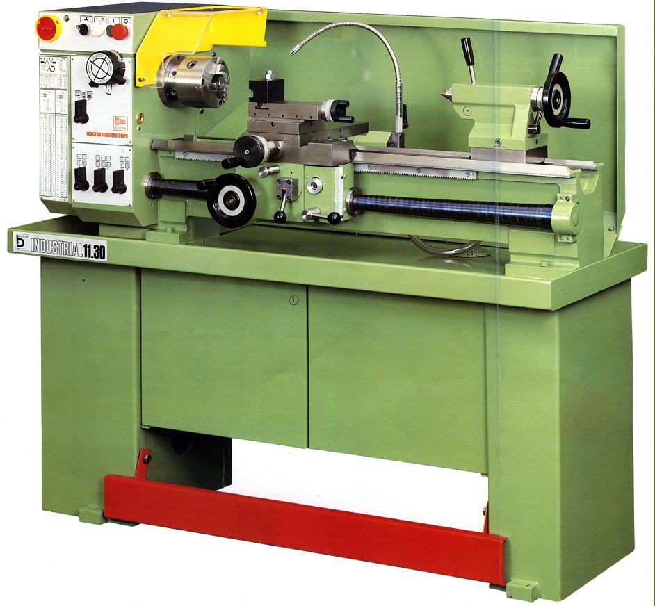
Boxford 11.30 - also built as the 11-20, 10-30 and 10.20
|
|
|
|
|
|
|
|
|
Continued:
Boxford 11-30, 11-20 and 10-30 Industrial Lathes
Named after their capacity - nominal swings of 11 inches and 10 inches (5.5 and 5-inch centre heights) these four lathes were the basic machines of the Industrial range with the other pair, the TR.11.30 Toolroom and 330IS, being somewhat more expensive - although they did share a large number of components.
Apart for their actual centre heights of 145 mm (5.69") and 132 mm (5.19"), the lathes all had an identical specification and could be ordered with either 20" (500 mm) or 30" (1000 mm) between centres. On each version, as with other lathes in Boxford's new range, the rear bed V-way was cut away under the spindle for a length of 150 mm (6") to give a slightly increased swing.
Induction hardened and ground as standard, the 190 mm (7.5") wide bed was heavy and rigid and equipped with V and flat ways; it was carried on a robust cabinet stand with a lockable storage cupboard and a full-length splashback.
With a 35 mm (1.375") bore and a hardened D1-3" nose fitted with a No.4.5 ASA.B5.10 bush (machined down, internally, to a No. 3 Morse taper), the spindle ran in Timken taper-roller bearings. Fastened to an adjustable plate behind and below the headstock, a choice of two motors (and speed ranges) was offered, one 3-phase the other 1-phase. On the former a 1.1 kW (1.5 h.p.) gave 9 speeds spanning 40 to 2240 r.p.m. while on the latter a 0.55 kW (0.75 h.p.) produced 9 speeds from 27 to 1490 r.p.m.
Well-supported, the spindle, together with the splash lubricated, hardened and ground headstock gears (that had been finished on state-of-the-art Reishaur machines), ensured that the lathe made little noise - the maximum level being some 83 Dba. Spindle-speed control (as on all industrial models) was by a pair of concentrically-mounted dials of the safety-type that had to be pushed and turned to operate.
All within easy reach, the electrical controls were clustered across the top of the headstock's front face and included an emergency stop button and an isolator switch that could be padlocked. Safety micro-switches that cut the main motor were fitted to the chuck guard and changewheel cover while a full-length safety kick stop was available to fit across the stand at floor level.
Running in sealed-for-life ball races, the 25 mm (1") diameter telescopic spring-cover guarded leadscrew could be had with either a 6 mm or 4 t.p.i. pitch. It was driven by a fully enclosed, all-lever-operated dual English/Metric screwcutting and feeds gearbox that provided 39 metric threads from 0.2 to 7 mm and 34 English from 3.5 to 80 t.p.i. By substituting 4 changewheels BA pitches from 0 to 8 BA could be generated and, with 2 additional changewheels and an auxiliary mounting stud, twelve Module pitches from 0.3 to 2 MOD together with 24 Diametral (DP) from 14 to 60 DP. A thread-dial-thread indicator was built into the front face of the apron. As a point of interest, the screwcutting and feeds gearbox and apron were both packed from new with Shell Alvainia R1 grease - or its equivalent - and under normal working conditions should not require any further lubrication.
Twelve rates of sliding and surfacing feeds were provided, the former from 0.12 mm (0.0005") to 0.6 mm (0.024") per rev and the latter at exactly half as fast.
Completely sealed (and packed from new with Shell Alvainia R1 grease (or its equivalent) the apron had controls consisting of a carriage handwheel with micrometer dial, a simple push/pull button to select the power feed direction and a lift-and-lower lever engaged the feeds - the drive passing through an adjustable apron-mounted torque-limiting clutch, with further protection provided by a brass shear pin in the changewheel drive.
Fitted with a full length cross slide 140 mm (5.5") wide with 175 mm (6.875") of travel, the compound slide rest was heavily built, with locks on both slides (one of the central gib adjustment screws being adapted for the purpose), and fitted with crisply engraved, satin-chrome finished zeroing micrometer dials - that on the cross slide being of a usefully large diameter and easy to read (the divisions giving a direct reading of the reduction in diameter). The T-slotted top slide could be rotated through 360°, had a travel of 3.75 inches and was equipped with just a simple block toolpost able to take tools up to 12 mm (0.5") square. Both top and cross slides had a row of closely spaced gib-strip adjustment screws of the self-locking type,
Travel of the set-over tailstock's large diameter (37 mm (1.47") No. 3 Morse taper spindle was 95 mm (3.75") with a dual-reading inch/metric micrometer dial to help gauge the setting. A powerful split-barrel from of spindle lock was fitted, operated by a usefully long handle.
A wide range of accessories was offered including some, such as Low-voltage halogen lighting, a spindle brake and coolant that should have been fitted as standard. Other items listed were: a quick-set toolpost; dual inch/metric feed dials; taper turning; high-speed threading; hydraulic copying; digital readouts of carriage and cross-slide travels; rear-mounted motorised milling and drilling attachments; 6-station bed-mounted capstan unit; toolpost grinder; pneumatic chucks; super-precision direct-mounting 3-jaw chucks; a 12-inch faceplate; 48-position indexing 4-way toolpost; rear toolpost and accessories; milling, dividing and gear-cutting attachments (using cutters mounted in the chuck); fixed and travelling steadies; plain and micrometer carriage stops; cross slide stops; travelling work guards and half and full-length T-slotted milling and boring tables.
Continued below:
|
|
|
|
|
|
|
|
|
|
|
|
|
|
 |
|
|
|
|
|
|
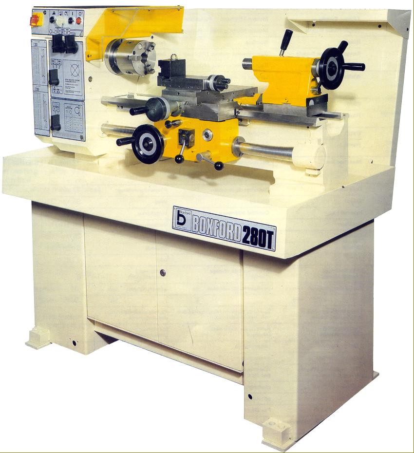
Boxford 280T Training Lathe
Continued:
Boxford 280T Training Lathe
Less well specified than the 3330TR-based Model 280 Trainer, the 280T shared the majority of its components with the Boxford Industrial and T-Type training lathes and was virtually identical in specification to the latter type, differing only in having its centre height increased from 132 to 145 mm (to match the Toolroom TR.11.30 and "Industrial 11-inch" models). Able to be ordered with either 20 or 30 inches between centres, it had a heavy and rigid induction hardened and ground bed 190 mm (7.5") wide with V and flat ways and, as on all versions of these lathes, with the rear bed V-way was cut away under the spindle for a length of 150 mm (6") to give a slightly increased swing. The machine was carried on a robust cabinet stand with a lockable storage cupboard and full-length splash back that incorporated a tool tray.
With a 35 mm (1.375") bore and a hardened D1-3" nose fitted with a No. 4.5 ASA.B5.10 bush machined down, internally, to a No. 3 Morse taper, the spindle ran in Timken taper roller bearings. Powered by either a 3-phase 1.5 kW (2 h.p.) or 1-phase 0.55 kW (750 kW) motor fastened to an adjustable plate behind and below the headstock, in both cases the six spindle speeds spanned a 65 to 15000 r.p.m. The well-supported spindle, together with the splash lubricated, hardened and ground headstock gears (that had been finished on state-of-the-art Reishaur machines), ensured that the lathe ran quietly. Spindle-speed control differed from that on the Industrial models, the dial system being replaced by a pair of push-in-and-turn levers.
All within easy reach, the electrical controls were clustered across the top of the headstock's front face and included an emergency stop button and an isolator switch that could be padlocked. Safety micro-switches that cut the main motor were fitted to the chuck guard and changewheel cover, while a full-length safety kick stop was available to fit across the front of the stand at floor level.
Running in sealed-for-life ball races, the 25 mm (1") diameter telescopic spring-cover guarded leadscrew could be had with either a 6 mm or 4 t.p.i. pitch. It was driven by changewheels that could, without being disturbed, generate metric pitches of 0.4. 0.8, 1, 2 and 4 mm and English of 6, 12, 30 and 60 t.p.i. Feed rates with these gears ranged from 0.04 to 4 mm per rev (0.0015 to 0.016") sliding - and at half that speed when surfacing. With additional changewheels, 28 metric threads from 0.4 to 4 mm pitch could be generated as well as 28 English from 5 to 72 t.p.i., 12 Module from 0.3 to 2 MOD and 25 Diametral from 14 to 60 DP. A thread-dial-thread indicator was built, as part of the standard specification, into the front face of the apron.
Completely sealed and packed with Shell Alvainia R1 grease - or its equivalent - from new, the apron had controls consisting of a carriage handwheel with micrometer dial, a simple push/pull button to select the power feed direction and a lift-and-lower lever engaged the feeds - the drive passing through an adjustable, apron-mounted torque-limiting clutch, with further protection provided by a brass shear pin in the changewheel drive.
Fitted with a full length cross slide 140 mm (5.5") wide with 175 mm (6.875") of travel, the compound slide rest was heavily built, with locks on both slides (one of the central gib adjustment screws being adapted for the purpose), and fitted with crisply engraved, satin-chrome finished zeroing micrometer dials - that on the cross slide being of a usefully large diameter and easy to read (the divisions giving a direct reading of the reduction in diameter). The T-slotted top slide could be rotated through 360°, had a travel of 3.75 inches and was equipped with a simple toolpost able to take tools up to 12 mm (0.5") square.
Travel of the set-over tailstock's large diameter 37 mm (1.47") No. 3 Morse taper spindle was 95 mm (3.75") with a dual-reading inch/metric micrometer dial to help gauge the setting. A powerful split-barrel from of spindle lock was fitted, operated by a usefully long handle.
A wide range of accessories was offered including some, such as Low-voltage halogen lighting and coolant that should have been fitted as standard. Other items listed were: taper turning; high-speed threading; hydraulic copying; digital readouts of carriage and cross-slide travels; rear-mounted motorised milling and drilling attachments; 6-station bed-mounted capstan unit; toolpost grinder; pneumatic chucks; super-precision direct-mounting 3-jaw chucks; an 11-inch faceplate; 48-position indexing 4-way toolpost; a simple single block toolpost able to take a single tool up to 12 mm (0.5") square; rear toolpost and accessories; milling, dividing and gear-cutting attachments (using cutters mounted in the chuck); fixed and travelling steadies; plain and micrometer carriage stops; cross slide stops and a T-slotted boring table.
Continued below:
|
|
|
|
|
|
|
|
|
|
|
|
|
|
 |
|
|
|
|
|
|
Continued:
Boxford T-Series Training Lathes
Although constructed from a large number of common parts, the Boxford T-Series training lathes are easily distinguished from their industrial brothers by a pair of push-in-and-turn levers instead of a dial to change spindle speeds. Badged according to their specification, centre height and distance between centres, the range consisted of the well-specified STS followed in order of the demising number of features includes as TS, TF and TH. A typical badge might have read: "TS 20-10" indicating a swing of 10" and a between-centres' capacity of 20".
All versions had a centre height of 132 mm (5.19"), admitted 500 mm (20") between centres (though optionally 1000 mm/30" on just the STS) and were identical in basic construction, capacity and spindle speeds - only the screwcutting arrangements distinguishing one model from another.
All had a heavy and rigid bed (induction hardened and ground as standard) that was 190 mm (7.5") wide with V and flat ways with rear bed V-way cut away under the spindle for a length of 150 mm (6") to give a slightly increased swing. The machine was carried on a robust cabinet stand with a lockable storage cupboard and full-length splash back - but a tool tray.
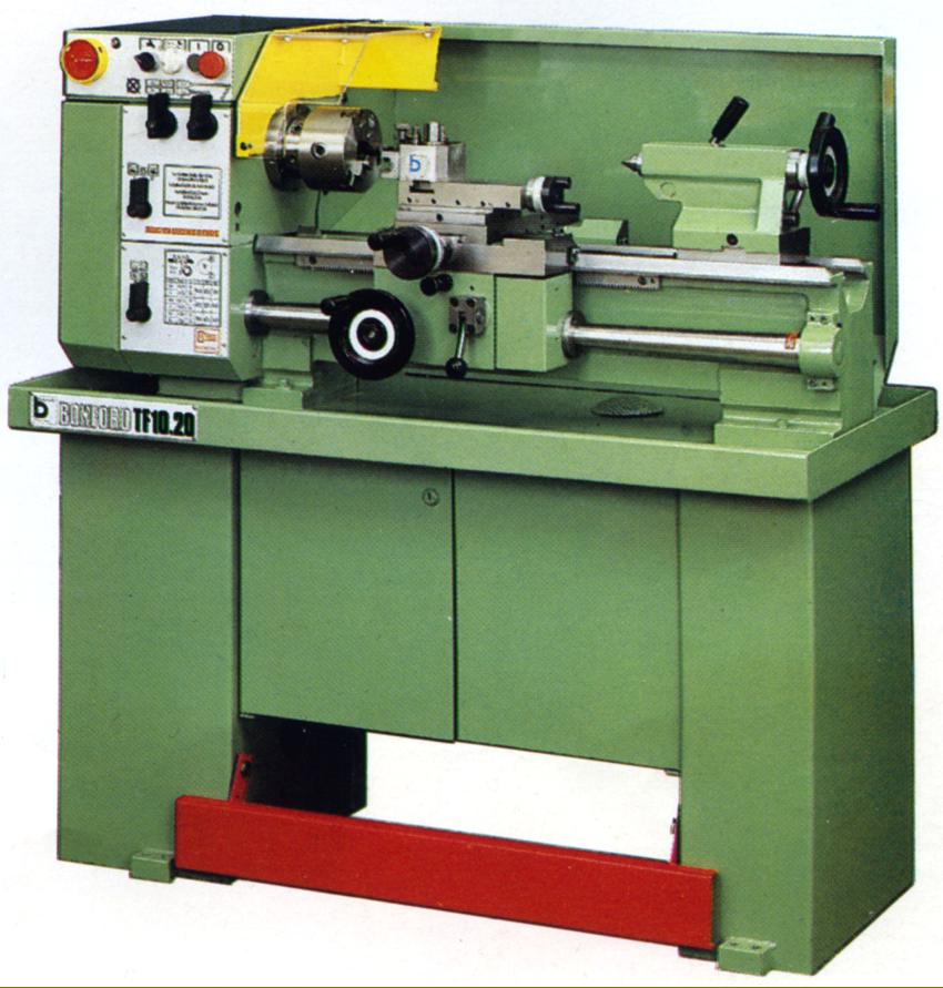
Bottom of the range was the (rare) plain-turning TH, a machine bereft of leadscrew and so any sort of power feed. The TF, fitted with changewheels and a 25 mm (1") diameter telescopic spring-cover guarded leadscrew running in sealed-for-life ball races was arranged to provided 6 rates of power feed, but was not intended for screwcutting. Feed rates ran from 0.04 mm to 0.4 mm (0.0015" to 0.16") per rev. sliding and half as fast surfacing. The very similar TS provided the same number and rates of power feed and, in addition (by using changewheels), 23 inch pitches from 0.5 to 72 t.p.i. and 21 metric from 0.4 to 4 mm. With additional changewheels BA threads from 0 to 6 could be generated and, by adding an extra changewheel stud and gears, eight Module pitches from 0.3 to 1 MOD and 19 Diametral from 20 to 60 DP.
Top of the range was the STS, a lathe virtually identical to the 10.30 Industrial model with a fully enclosed, all-lever-operated, dual English/Metric screwcutting and feeds gearbox that provided 39 metric threads from 0.2 to 7 mm and 34 English from 3.5 to 80 t.p.i. By substituting 4 changewheels BA pitches from 0 to 8 BA could be generated and, with 2 additional changewheels and an auxiliary mounting stud, twelve Module pitches from 0.3 to 2 MOD together with 24 Diametral (DP) from 14 to 60 DP. Twelve rates of sliding and surfacing feeds were provided, the former from 0.12 mm (0.0005") to 0.6 mm (0.024") per rev and the latter at exactly half that rate. On all the screwcutting versions a thread-dial-thread indicator was built into the front face of the apron. As a point of interest, the screwcutting and feeds gearbox and apron were both packed from new with Shell Alvainia R1 grease - or its equivalent - and under normal working conditions should not require any further lubrication.
All types shared the same bed: 190 mm (7.5") wide, heavily built and rigid it was induction hardened and ground as standard and equipped with V and flat ways. A robust, all-steel cabinet stand was provided, complete with a lockable storage cupboard and full-length splash back.
With a 35 mm (1.375") bore and a hardened D1-3" nose fitted with a No.4.5 ASA.B5.10 bush (machined down, internally, to a No. 3 Morse taper), the spindle ran in Timken taper-roller bearings. Fastened to an adjustable plate behind and below the headstock, the motor on the STS was either a 3-phase 1.1 kW (1.5 h.p.) or a 1-phase 0.55 kW (0.75 h.p.), both giving 6 speeds that spanned 43 to 1000 r.p.m. All other models had the same range and number of speeds but were supplied with a 0.55 kW (0.75 h.p.) unit in either 3 or 1-phase form. Spindle-speed control differed from that on the Industrial models, the dial system being replaced by a pair of push-in-and-turn levers.
Continued below:
|
|
|
|
|
|
|
|
|
|
|
|
|
|
 |
|
|
|
|
|
|
Boxford TF10.20 Training Lathe. Note the single lever on the face of the headstock in line with the leadscrew--this indicating a cheaper model with screwcutting by changewheels.
Continued:
Well-supported, the spindle, together with the splash lubricated, hardened and ground headstock gears (that had been finished on state-of-the-art Reishaur machines), ensured that the lathe made little noise. All within easy reach, the electrical controls were clustered across the top of the headstock's front face and included an emergency stop button and an isolator switch that could be padlocked. Safety micro-switches that cut the main motor were fitted to the chuck guard and changewheel cover while a full-length safety kick stop was available to fit across the stand at floor level.
Completely sealed and packed from new with Shell Alvainia R1 grease - or its equivalent - the apron had controls consisting of a carriage handwheel with micrometer dial, a simple push/pull button to select the power feed direction and a lift-and-lower lever engaged the feeds - the drive passing through an adjustable apron-mounted torque-limiting clutch, with further protection provided by a brass shear pin in the changewheel drive.
Fitted with a full length cross slide 140 mm (5.5") wide with 175 mm (6.875") of travel, the compound slide rest was heavily built, with locks on both slides (one of the central gib adjustment screws being adapted for the purpose), and fitted with crisply engraved, satin-chrome finished zeroing micrometer dials - that on the cross slide being of a usefully large diameter and easy to read (the divisions giving a direct reading of the reduction in diameter). The T-slotted top slide could be rotated through 360°, had a travel of 3.75 inches and was (surprisingly) equipped with a Dickson Quick-set toolpost - though only two holders were provided, a standard and parting off. Both top and cross slides had a row of closely-spaced gib-strip adjustment screws of the self-locking type,
Travel of the set-over tailstock's large diameter (37 mm (1.47") No. 3 Morse taper spindle was 95 mm (3.75") with a dual-reading inch/metric micrometer dial to help gauge the setting. A powerful split-barrel from of spindle lock was fitted, operated by a usefully long handle.
A wide range of accessories was offered including some, such as Low-voltage halogen lighting, a spindle brake and coolant that should have been fitted as standard. Other items listed were: a quick-set toolpost; dual inch/metric feed dials; taper turning; high-speed threading; hydraulic copying; digital readouts of carriage and cross-slide travels; rear-mounted motorised milling and drilling attachments; 6-station bed-mounted capstan unit; toolpost grinder; pneumatic chucks; super-precision direct-mounting 3-jaw chucks; a 12-inch faceplate; 48-position indexing 4-way toolpost; rear toolpost and accessories; milling, dividing and gear-cutting attachments (using cutters mounted in the chuck); fixed and travelling steadies; plain and micrometer carriage stops; cross slide stops; travelling work guards and half and full-length T-slotted milling and boring tables.
Continued below:
|
|
|
|
|
|
|
|
|
|
|
|
|
|
 |
|
|
|
|
|
|
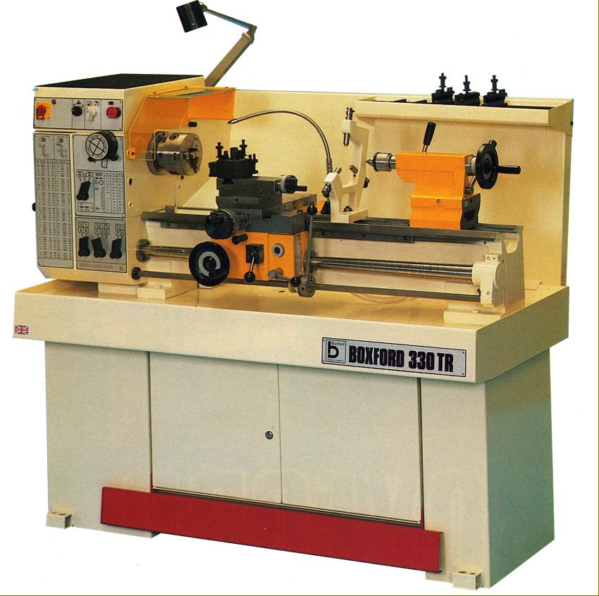
Boxford 330TR Toolroom
Continued:
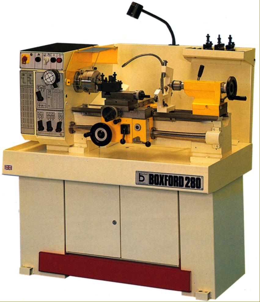
Although advertised as a toolroom lathe, the 330TR was not so highly specified as the TR.11.30 , it lacked the super-precision spindle bearings and was built to reach the ISO 1708 and DIN 8605 standards. It was produced in three models that shared the majority of their components: the fully specified TR with a 170 mm centre height, the less well equipped but same size Model 330 and the smaller 145 mm centre height 280 Trainer. The 330TR was offered with either 750 or 1000 mm between centres with the other two restricted to 500 or 750 mm.
Although the 330TR came reasonably well equipped with full coolant equipment (the tank positioned out of reach at the back of the machine) faceplate, catchplate, spindle nose adaptor, emergency stop foot-bar operating a powerful spindle brake, a powerful drive motor and dual-reading micrometer dials, on the other models these fittings were all at extra cost.
The three versions shared a heavy and rigid bed (induction hardened and ground as standard) that was 190 mm (7.5") wide with V and flat ways with rear bed V-way cut away under the spindle for a length of 150 mm (6") to give a slightly increased swing. The machine was carried on a robust cabinet stand with a lockable storage cupboard and full-length splash back that incorporated a tool tray.
With a 35 mm (1.375") bore and a hardened D1-3" nose fitted with a No.4.5 ASA.B5.10 bush machined down, internally, to a No. 3 Morse taper, the spindle ran in Timken taper roller bearings and was driven, on the 330TR by a 1.5 kW (2 h.p.) motor fastened to an adjustable plate behind and below the headstock. The same motor was available, at extra cost, the other two types but, as standard, these came equipped with a 0.95 kW (1.3 h.p.) unit. While the TR had nine seeds from 54 to 3000 r.p.m. the other two had their nine from 40 to 2240 r.p.m. - still an adequate range for the size of lathe. As an option all versions could be fitted with a 2-speed 1.9/0.95 kW (2.5/1.3 h.p.) motor that gave eighteen speeds from to 3000 r.p.m., an almost perfect range that allowed both safe screwcutting (and the turning of large diameters) while also being able to cope with the high speeds need for small components. A single-phase motor was also listed: of 0.95 kW (1.3 h.p.) this gave nine speeds from 27 to 1490, a range more suitable for training workshops.
Speeds (as on all Toolroom and Industrial versions) were changed by two concentrically mounted dials equipped with short levers (even the 280 Trainer retaining this system instead of being fitted with the more normal twin-lever arrangement). The well-supported spindle, together with the splash lubricated, hardened and ground headstock gears (that had been finished on state-of-the-art Reishaur machines), ensured that the lathe made little noise.
All within easy reach, the electrical controls were clustered across the top of the headstock's front face and included an emergency stop button and an isolator switch that could be padlocked. Safety micro-switches that cut the main motor were fitted to the chuck guard and changewheel cover while a full-length safety kick stop was standard on the 33TR and extra on the other models.
Running in sealed-for-life ball races, the 25 mm (1") diameter telescopic spring-cover guarded leadscrew could be had with either a 6 mm or 4 t.p.i. pitch. It was driven by a fully enclosed, all-lever-operated dual English/Metric screwcutting and feeds gearbox that provided 39 metric threads from 0.2 to 7 mm and 34 English from 3.5 to 80 t.p.i. By substituting 4 changewheels BA pitches from 0 to 8 BA could be generated and, with 2 additional changewheels and an auxiliary mounting stud, twelve Module pitches from 0.3 to 2 MOD together with 24 Diametral (DP) from 14 to 60 DP. A thread-dial-thread indicator was built into the front face of the apron. As a point of interest, the screwcutting and feeds gearbox and apron were both packed from new with Shell Alvainia R1 grease - or its equivalent - and under normal working conditions should not require any further lubrication.
Unusually found finished in white with a yellow tailstock and apron, the TR.11.30 might also, in later years, have been given a two-tone green finish.
Twelve rates of sliding and surfacing feeds were provided, the former from 0.12 mm (0.0005") to 0.6 mm (0.024") per rev and the latter at exactly half that rate.
Completely sealed and with the internals running in an oil bath, the apron had controls consisting of a carriage handwheel with micrometer dial, a simple push/pull button to select the power feed direction and a lift-and-lower lever engaged the feeds - the drive passing through an adjustable apron-mounted torque-limiting clutch, with further protection provided by a brass shear pin in the changewheel drive.
Fitted with a full length cross slide 140 mm (5.5") wide with 175 mm (6.875") of travel, the compound slide rest was heavily built, with locks on both slides (one of the central gib adjustment screws being adapted for the purpose), and fitted with crisply engraved, satin-chrome finished zeroing micrometer dials - that on the cross slide being of a usefully large diameter and easy to read (the divisions giving a direct reading of the reduction in diameter). The T-slotted top slide could be rotated through 360°, had a travel of 3.75 inches and was equipped with a Dickson quick-set toolpost - an ideal companion on this class of machine. As befitted a machine of this class, both slides had closely-spaced gib-strip adjustment screws of the self-locking type.
Travel of the set-over tailstock's large diameter (37 mm (1.47") No. 3 Morse taper spindle was 95 mm (3.75") with a dual-reading inch/metric micrometer dial to help gauge the setting. A powerful split-barrel from of spindle lock was fitted, operated by a usefully long handle.
A wide range of accessories was available, including (in addition to those already mentioned): low-voltage halogen lighting; taper turning; high-speed threading; hydraulic copying; digital readouts of carriage and cross-slide travels; rear-mounted motorised milling and drilling attachments; 6-station bed-mounted capstan unit; toolpost grinder; pneumatic chucks; super-precision direct-mounting 3-jaw chucks; an 11-inch faceplate; 48-position indexing 4-way toolpost; a simple single block toolpost able to take a single tool up to 12 mm (0.5") square; rear toolpost and accessories; milling, dividing and gear-cutting attachments (using cutters mounted in the chuck); fixed and travelling steadies; plain and micrometer carriage stops; cross slide stops and a T-slotted boring table..
|
|
|
|
|
|
|
|
|
|
|
|
|
|
 |
|
|
|
|
|
|
The smaller 145 mm centre height 280 Trainer version of the Type 330TR
|
|
|
|
|
|
|
|
|
|
|
|
|
|
 |
|
|
|
|
|
|
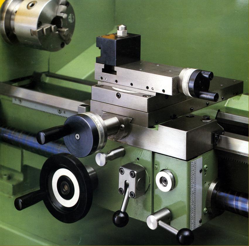
Typical carriage assembly as used across the range. Note the face-mounted thread-dial indicator
|
|
|
|
|
|
|
|
|
|
|
 |
|
|
|
|
|
|
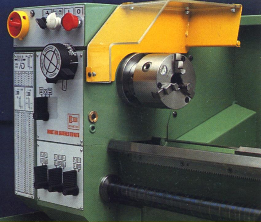
Headstock and screwcutting gearbox typical of those used on the Toolroom and Industrial versions of the lathe
|
|
|
|
|
|
|
|
 |
|
|
|
|
|
|
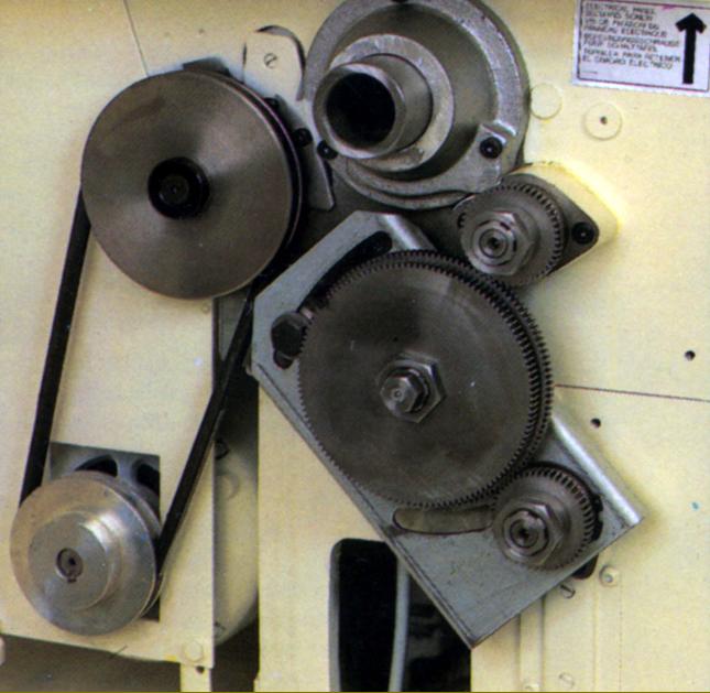
Drive and changewheel arrangement common to all types
|
|
|
|
|
|
|
|
|
|
|
|
|
|
 |
|
|
|
|
|
|
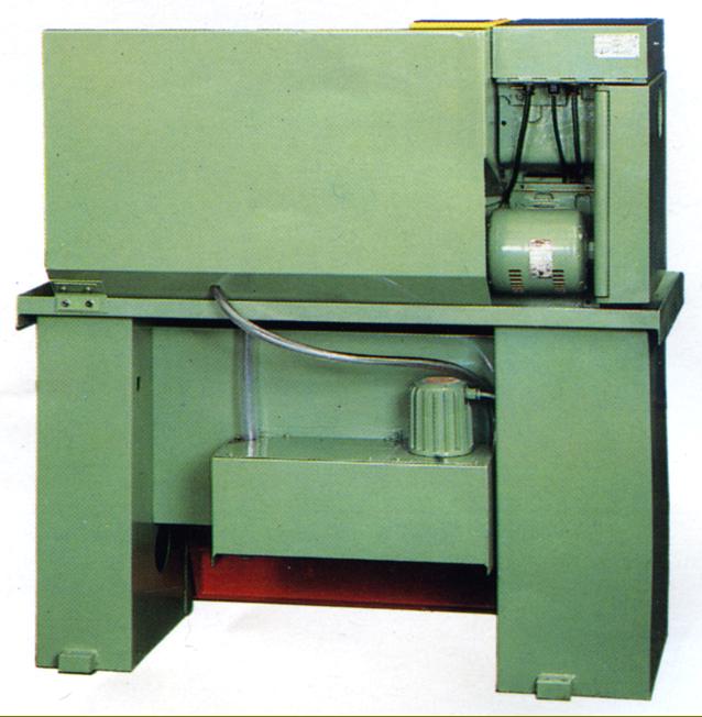
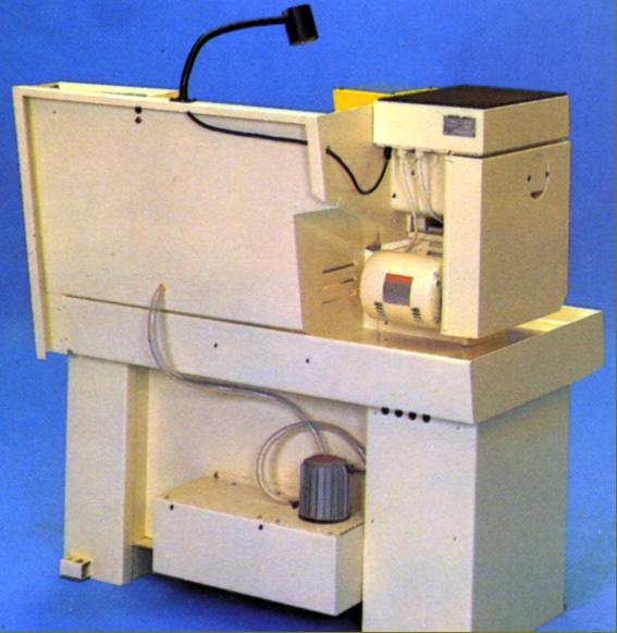
Tidy but inconvenient mounting of the coolant tank and pump
|
|
|
|
|
|
|
|
 |
|
|
|
|
|
|
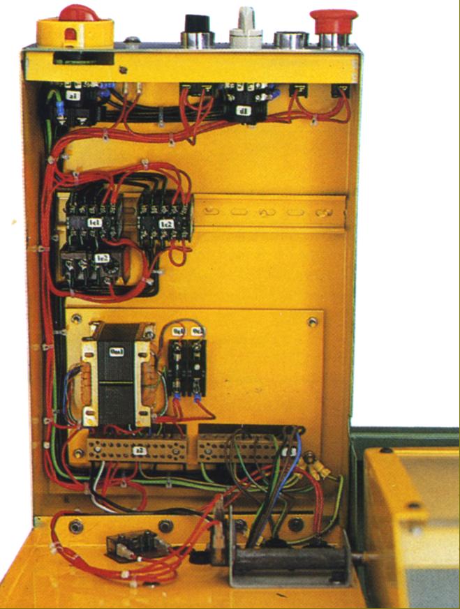
Neat arrangement of the electrical switchgear
|
|
|
|
|
|
|
|
 |
|
|
|
|
|
|
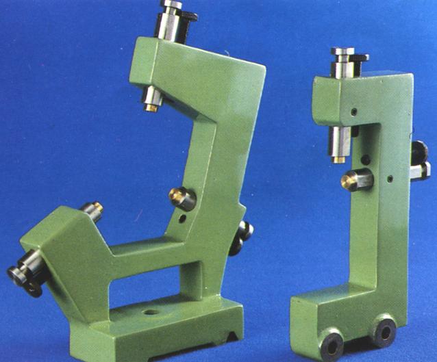
Distinctive fixed and travelling steadies
|
|
|
|
|
|
|
|
 |
|
|
|
|
|
|
|
|
|
|
|
|
|
|
|
An Operation, Maintenance and Parts Manual
is available for these lathes.
Late-type
Boxford Industrial & Training Lathes
289, 280T, STS 10.20, TS 10.20, TF 10.20, TH 10.20, 330TR, TR.11.30, 330, 280, 280T, 330IS, 280IS, 250IS, 11.30, 11.20, 10.30 and 10.20
email: tony@lathes.co.uk
Home Machine Tool Archive Machine-tools for Sale & Wanted
Machine Tool Manuals Machine Tool Catalogues Belts
Books Accessories
|
|
|
|
|
|