|
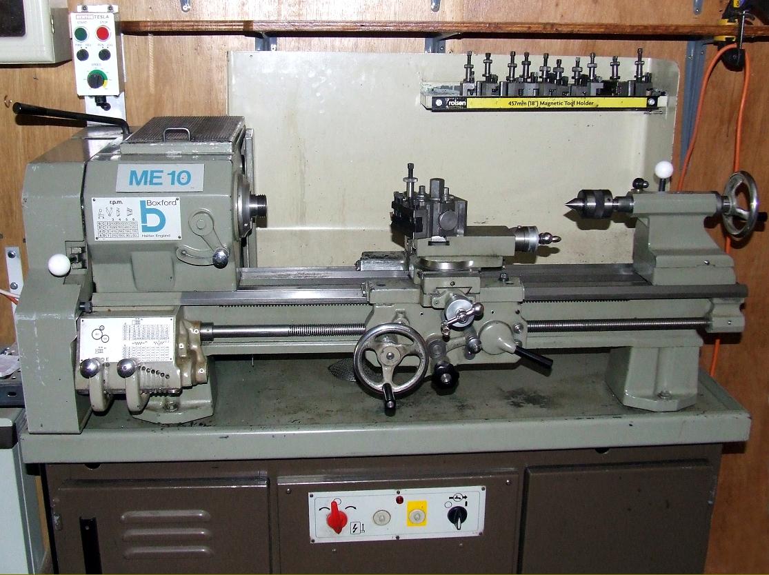
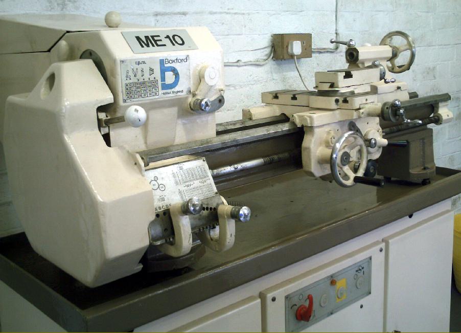
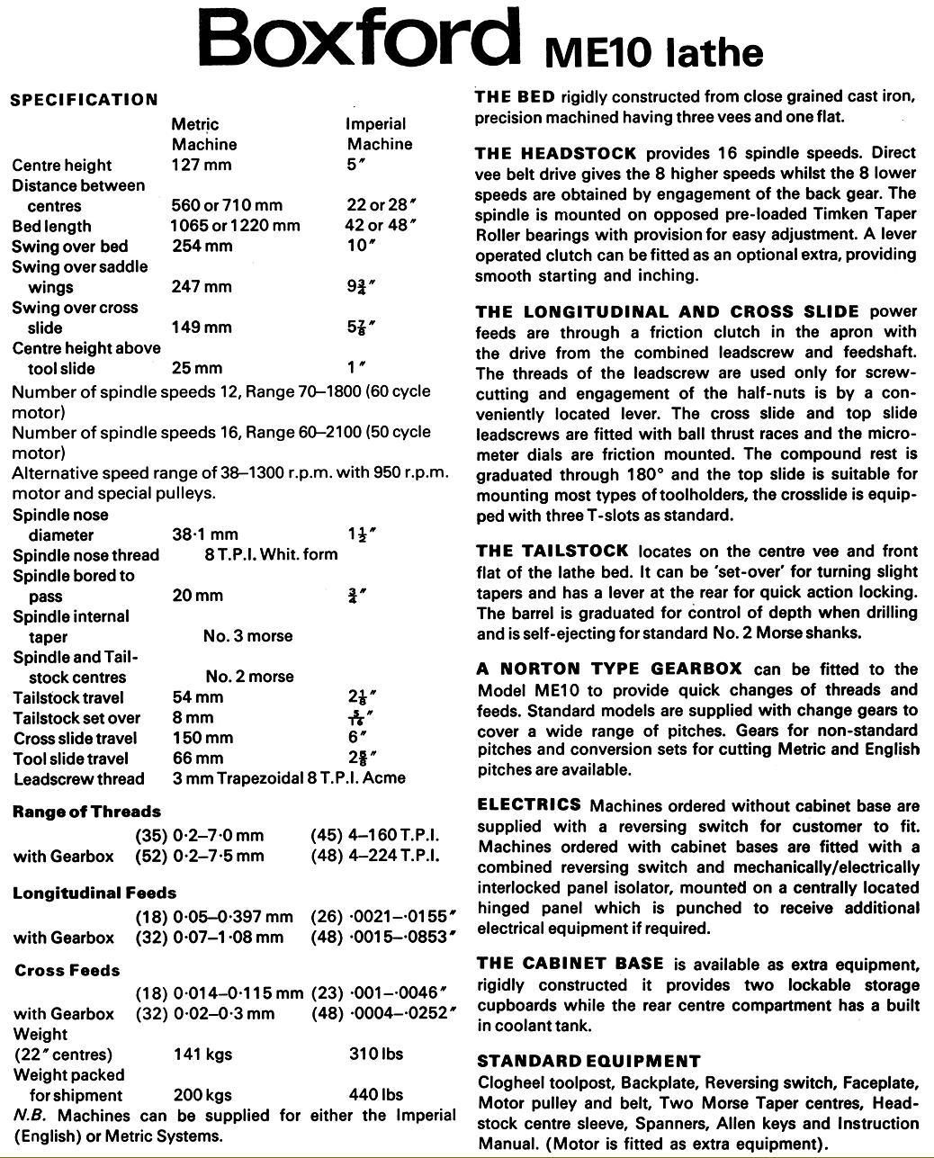
In November 1976 Boxford began to market the 5" x 22" and 28" (127 x 560 and 710 mm) Model ME10, a less expensive lathe - though constructed from components identical to machines higher up in the price range. Also available mounted on a special stand, the lathe was intended to run alongside the under-drive and rear-drive models and could be had in any of the three usual Boxford specifications: A (gearbox and power feeds), B (changewheels with power feeds) and C (changewheels and hand-driven cross feed). Mechanical details were also identical and can be found in detail on the main Boxford home page - though to summarise: a main spindle bored through 3/4" with a 1.5-inch 8 t.p.i. nose that took a special sleeve-down adapter to accept a No. 3 Morse taper centre. The tailstock - with a No. 2 Morse taper tailstock barrel that usually carried dual inch and mm ruler engravings and with a travel of 2.125" - could be set over for the turning of slight tapers. Equipped with changewheels the normal threading range was from 4 to 160 t.p.i. Imperial and 0.2 to 7 mm metric but with a screwcutting gearbox the range ran from 4 to 224 t.p.i. Imperial or 0.2 to 7.5 mm metric (a full specification sheet is shown at the bottom of the page).
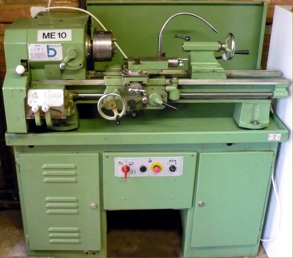
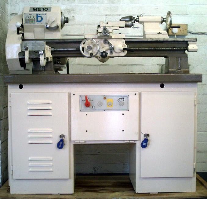
Early ME10s had a normal, full-length rear countershaft and were little different to the ordinary rear-drive models - the aim, presumably, being to use up supplies of no-longer-needed parts as the successful under-drive models took over. Numbers built using the full-length countershaft must have been limited for most are found with a much more compact design that significantly reduced amount of room required to install the machine; indeed, as a consequence, fitted to its own cabinet, the ME10 took up only a little more depth than the under-drive versions. Thus, the end result was an arrangement that made the lathe much more suitable for the home workshop - the market segment that Boxford must have been targeting and, indeed, advertised it for.
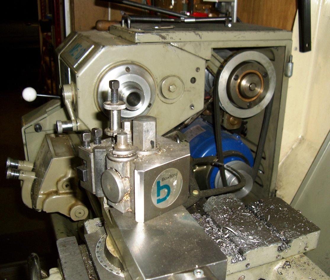
In order to achieve the reduction in back-to-front depth the countershaft was completely redesigned; it was available in standard form without a clutch or, at considerable extra cost, with. The assembly consisted of two brackets bolted to the back of the headstock with each carrying, at the top, an ear into which was threaded an inwards facing stud from which hung a "swing-head" casting formed, at the rear, into two bearing housings. The lower part of the countershaft consisted of a block of cast iron secured by a single clamp bolt to the bed V-way at the back of headstock; the block was bored through to take a bar, from which hung the slotted motor-support plate - this being secured at the bottom by a single shaft that incorporated a long compression spring - presumably to allow some "give" in the system. The "swing head" that carried the 4-step "A-section" V-belt pulley was tightened and relaxed by usual adjustable, over-centre mechanism with a right-and-left-hand threaded hexagon block fitted with a rather short and so awkward-to-manipulate ball-ended handle (the same fitting can be found on the original 1933 South Bend).
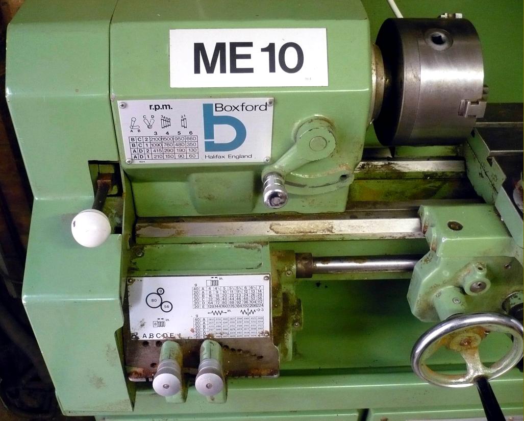
Lathes could be supplied with either eight or sixteen speeds, the difference being achieved by using either a single or double pulley arrangement of the motor-to-countershaft drive. The 2-step motor pulley was the same size as employed on other models but the matching pair on the countershaft were, due to the lack of room under the cover, forced to be rather smaller - the result being that bottom speed was raised to 60 and the top to 2100 r.p.m. against the more normal 30 to 1300 r.p.m. of the ordinary rear-drive models and 40 to 1400 r.p.m. of the under-drive type. However, at extra cost and alternative 38 to 1300 r.p.m. speed range was listed, this involving a 950 r.p.m. motor and different pulleys. Export lathes to be run on a 60 cycle supply were listed as having 12 speeds from 70 to 1800 r.p.m. - this presumably being achieved by machining the headstock pulley with 3 instead of 4 steps
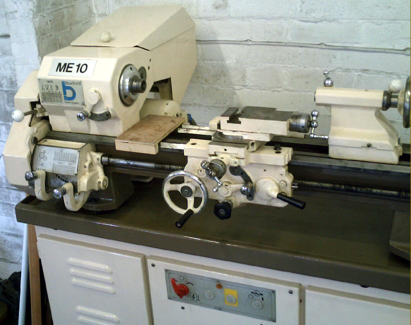
In order to lift the top belt-guard it was necessary to remove the clutch handle, this being a splined fit that also allowed it to be easily adjusted to the operator's preference. Interestingly the clutch unit was only ever offered on the ME10, no mention of it can be found in any literature relating to other Boxford models.
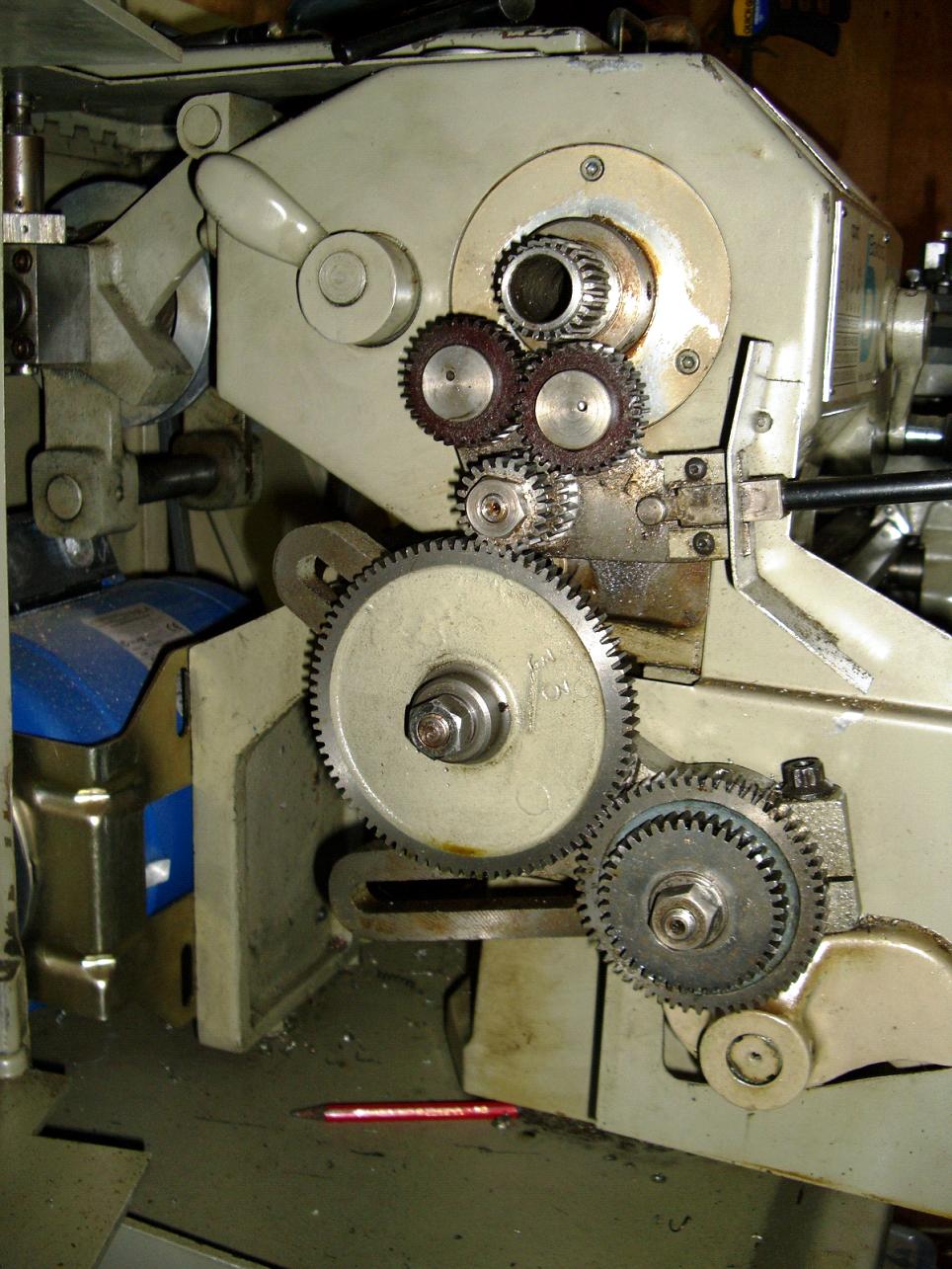
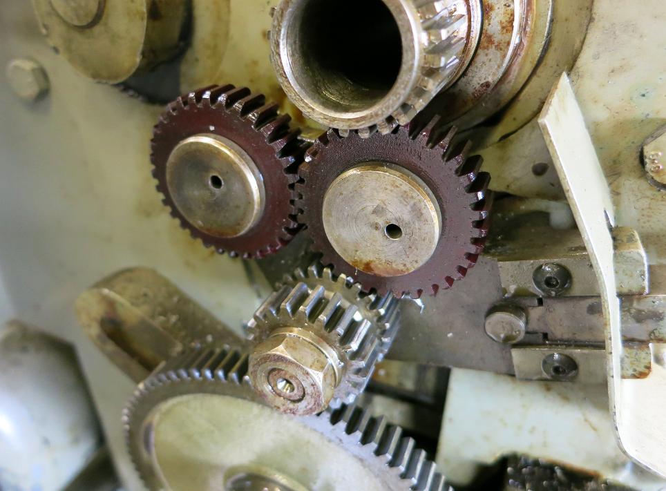
One difference on most of these lathes (though it's not certain that all were so equipped) was the use of quieter, Oilite-bushed, tumble-reverse gears in fibre that ran on needle-roller bearings. The fibre gears can be fitted to all other models and have definite advantages if the lathe is to be used where noise might be a problem - though being weaker the gears are, of course, if carelessly handled, more likely to fail.
In 1977 a basic long-bed ME10 (admitting 28 inches between centres) and fitted with power sliding and surfacing feed (Model ME10B) was listed at just £555, but adding those items necessary to make more readily useable - a screwcutting gearbox, a 5-inch Burnerd 3-jaw chuck, a Dickson quick-change toolpost, thread-dial indicator, faceplate, catchplate, 1/2" drill chuck, a pair of Morse centres, a T-slotted cross slide, a fixed steady an electric motor and switch and a cabinet stand - raised this to £1089 + 8% tax. Caused by a decade of relentless inflation under the Labour Party, by 1984 the same machine, with identical equipment, had risen to £2523 + the then 15% VAT.
|
|