|
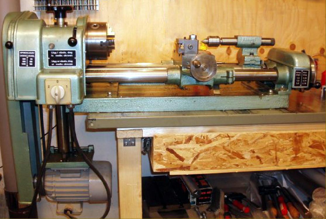
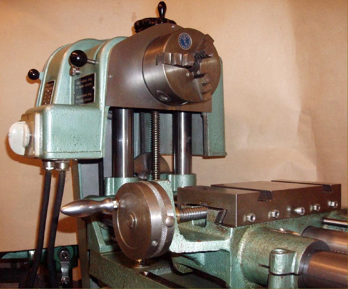
Manufactured in Eskilstuna, Sweden, by AB R.Almkvist & Co. the Pilot Universalmaskinen multi-purpose machine tool was constructed along lines often chosen for this class of lathe - a bar bed with elevating headstock - allowing the factory to produce an adaptable design for a reasonable price. With power-feed to the carriage - using conventional changewheels together with an additional gearbox at the tailstock end of the bed, the machine was unusual in several respects. The designer, struggling with the conflicting demands of a clean, modern appearance combined with a clever, versatile and adaptable mechanism, simply created the necessary mechanical parts and then hid them under detachable covers. Thus, the most difficult part of the machine to get right, the elevating backgeared headstock, had its prosaic looking components safely shielded and completely guarded. Whilst cosmetically and fiscally effective, this method contrasts strongly with the expensive and sophisticated Hommel/UWG, where no pretence at disguise was attempted.
Like the Hommel, the Almkvist was built up on a simple, rectangular cast-iron baseplate; however, there the similarity ended: at the tailstock end of the base a bolt-on casting doubled up to hold the end of the bed bars (two for the carriage and one for the tailstock, the latter also holding the drive shaft from the headstock) and a housing to contain a 3-speed carriage-feed gearbox. At the other end, the bed bars passed though a cast-in assembly bored to take two vertically disposed steel bars that carried the headstock at the top and the motor platform beneath. In addition, the headstock-end casting was used to mount the 2-speed carriage-feed gear train - simply sliding a pair of gears along their stud produced a slow or fast rate of feed. To operate the 3-speed gearbox a quadrant bracket had to be slackened and the drive gear, on the end of the leadscrew, slid in or out to engage with one of a cone of three pinions. Power feed rates totalled six: 0.09, 0.14, 0.18, 1.0, 1.5 and 2.0 mm per spindle revolution. The box also contained a lever-operated dog clutch that, once the gear train was in motion, allowed the drive to be flicked into and out of mesh. Astonishingly, the clutch operating mechanism, together with its mounting bracket, were in bronze. A usefully-large handwheel was fitted, complete with a very large-diameter micrometer dial and, to measure the travel of carriage and tailstock, a steel ruler was let into the length of the bed along its front edge.
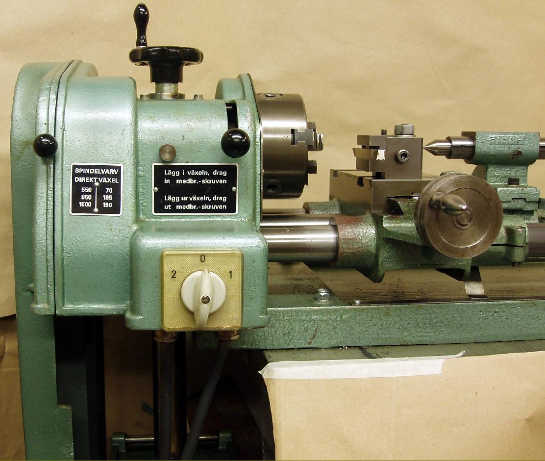
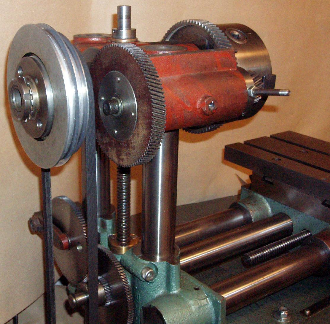
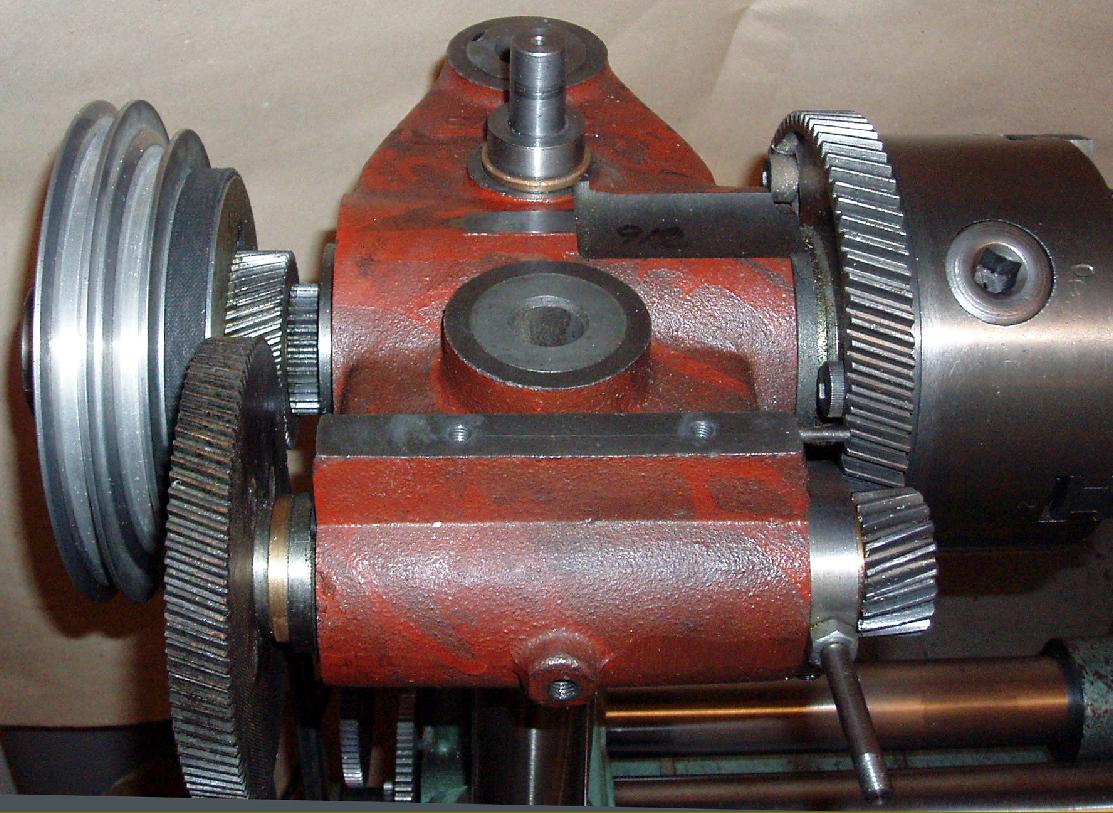
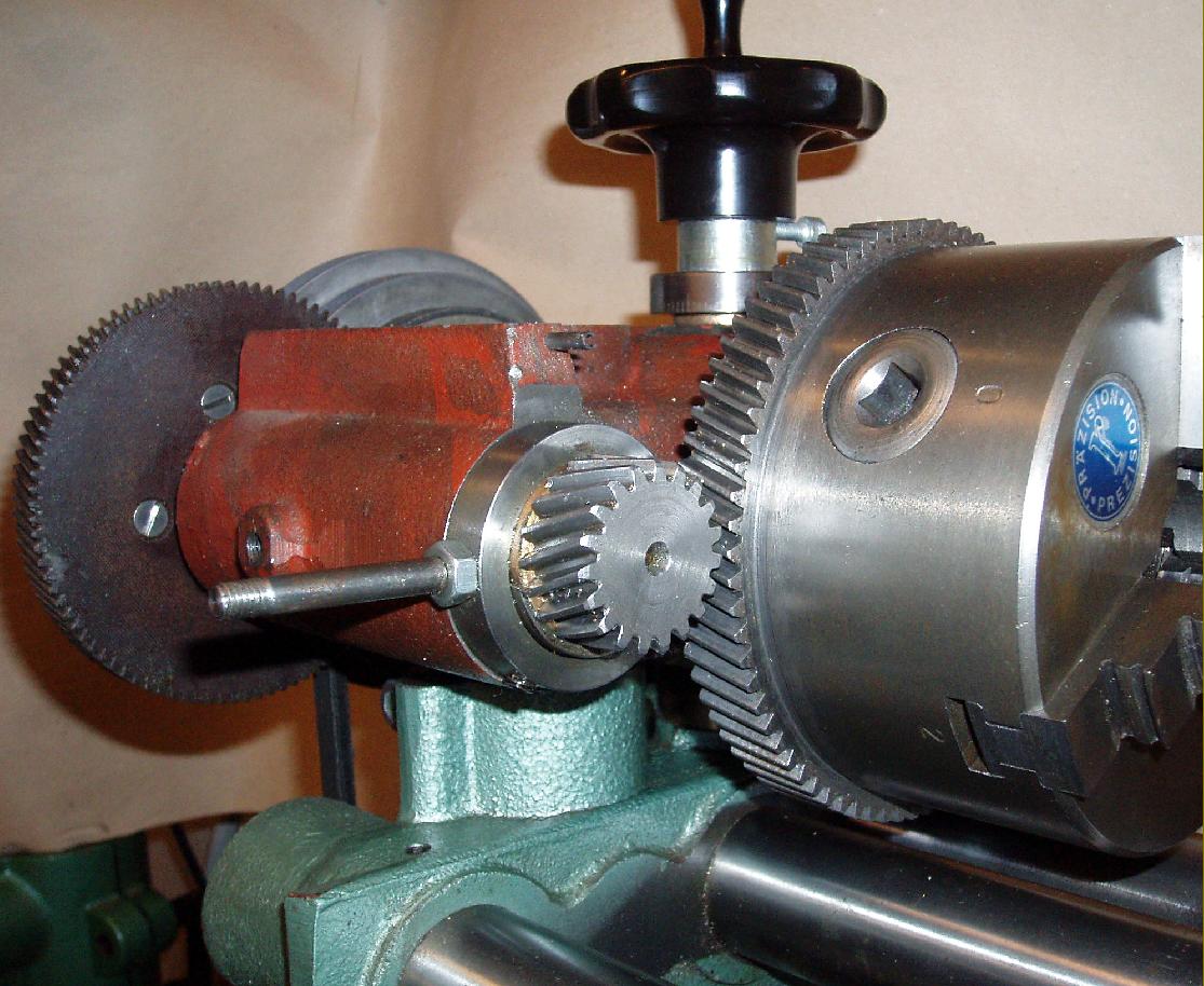
A consummate example of economical engineering, the headstock featured several money-saving ideas. The main, fully-boxed casting (being covered with a smooth casing) was left in its rough state with a 3-step, A-section pulley mounted outboard of the bearings. Bored through to clear 14 mm, the spindle ran in SKF taper roller bearings, had a No. 2 Morse taper nose and a bolt-on chuck - the front mounting flange for which, formed as part of the spindle, was machined to become the "bullwheel" part of the helical-form backgear assembly. The larger of the two eccentrically-mounted gears was in Tufnol - to promote quiet running and act as a safety device should anything untoward happen. The simple and cheap solution of using an outboard drive pulley allowed a completely enclosed, particularly stiff headstock assembly to be constructed - a design that, although much resisted by manufacturers over the years, slowly found favour during the 20th century. Today, most miniature lathes (Emco for example) use the layout - it was pioneered by Pultra in 1946 for high-class miniature precision lathes, with the 1920s EXE being the amongst first to use it for a series production screwcutting bench lathe.
Mounted at the bottom of the headstock elevation bars - a simple screw, topped by a plastic handwheel was used to lift and lower them - the 0.5 h.p. , 1500 r.p.m. 1-phase motor was bolted to a plate pivoted at its rear. The mechanism was crude: slackening the belt to change speeds required the loosening an Allen screw to allow a push-rod, sitting in a hole bored in the front elevating bar, to be moved upwards so allowing the plate to be lifted. When the speed change had been made, the belt had to be tensioned by pressing down on the plate (allowing the push rod to fall) before tightening the screw to lock everything in place. Six spindle speeds were available: 70, 105 and 190 r.p.m. in back gear and 550, 850 and 1500 r.p.m. in open drive.
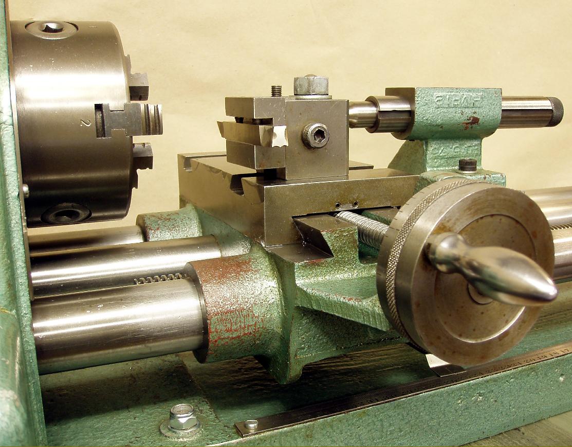
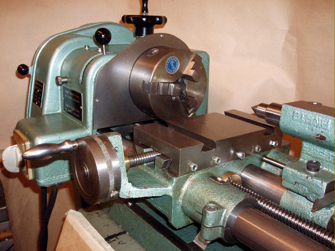
The carriage was rudimentary: just a smallish boring table with two V-shaped slots and insufficient room to mount a swivelling top slide when turning between centres. However, whilst many bar-bed lathes have a carriage no wider than the width of the cross slide, on the Almkvist things were much improved, with wings added at each side, front and back, for extra stability and to even out wear. A second, larger 2-slot slide was available to mount on top of the first and, as further compensation, the micrometer dial on the cross-feed screw was huge.
Able to be rotated slightly around its bed bar, the tailstock had a very simple "push" spindle - the necessary drive for drilling being obtained by passing a bar, screwed into the right-hand face of the carriage, through the unit to a "pull plate" - thus, moving the carriage towards the chuck pulled the tailstock with it. Used on large lathes, where the hand-drilling of large holes can become tedious if not impossible, one struggles to understand why the designer chose this particular mechanism - especially as the lack of any alternative, a screw or lever-feed for delicate work, must have put potential customers off. Unfortunately, unlike the Murad Bormilathe, the tailstock could not be elevated, so limiting the maximum diameter able to be turned between centres.
An interesting machine, the Pilot cannot really be considered a true "Universal". A very limited range of accessories was offered and, although it was adaptable for turning wooden bowls, simple milling by using a cutter in the chuck, drilling by clamping workpieces to the table and ordinary between-centres metal work, that was about the limit of its versatility.
If any reader has another example, or sales or technical literature, the writer would be very interested to hear from you..
|
|