|
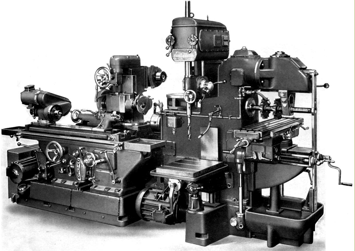
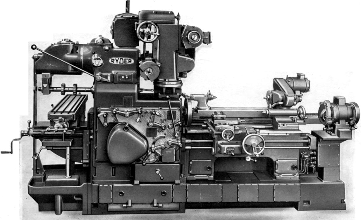
Machine Tool Manuals Machine Tool Catalogues Belts Adcock & Shipley Horizontal Millers Vertical Millers Adcock and Shipley manufactured and factored a vast range of engineering equipment including, from the early to late 1950s, two sizes of a remarkable "Universal Machine Tool", a machine not unlike that produced in Japan as the Dainichi. It was the built not in Adcock's Leicester factory, but at that of Thomas Ryder & Son Ltd. of Turner Bridge, Bolton. Ryder also sold the larger Universal under their own name - but were better known for their piston-ring machines, a small range of specialist lathes and the remarkable "Verticalauto", a vertical multi-spindle automatic that, despite sounding very Italian, was all-British. The smaller model is known to have been sold in two slightly different version, one being marked 739-Special and having its horizontal spindle enlarge from a 30 INT fitting to a No.40 and a form of 4-station quick-chage toolholder. |
|
|
|
Continued: |
|
|
|
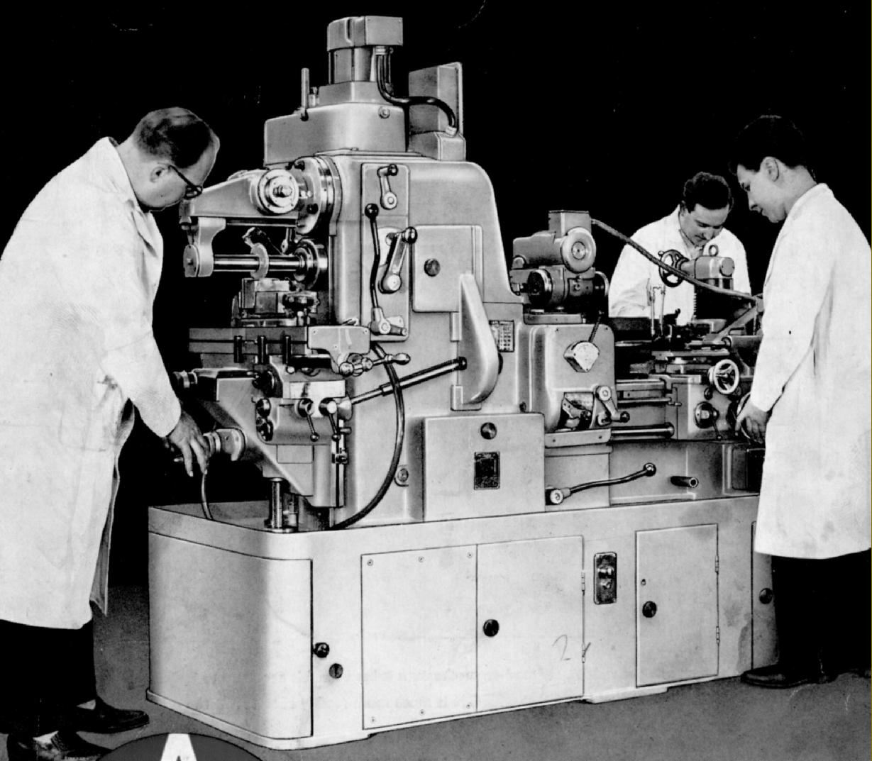
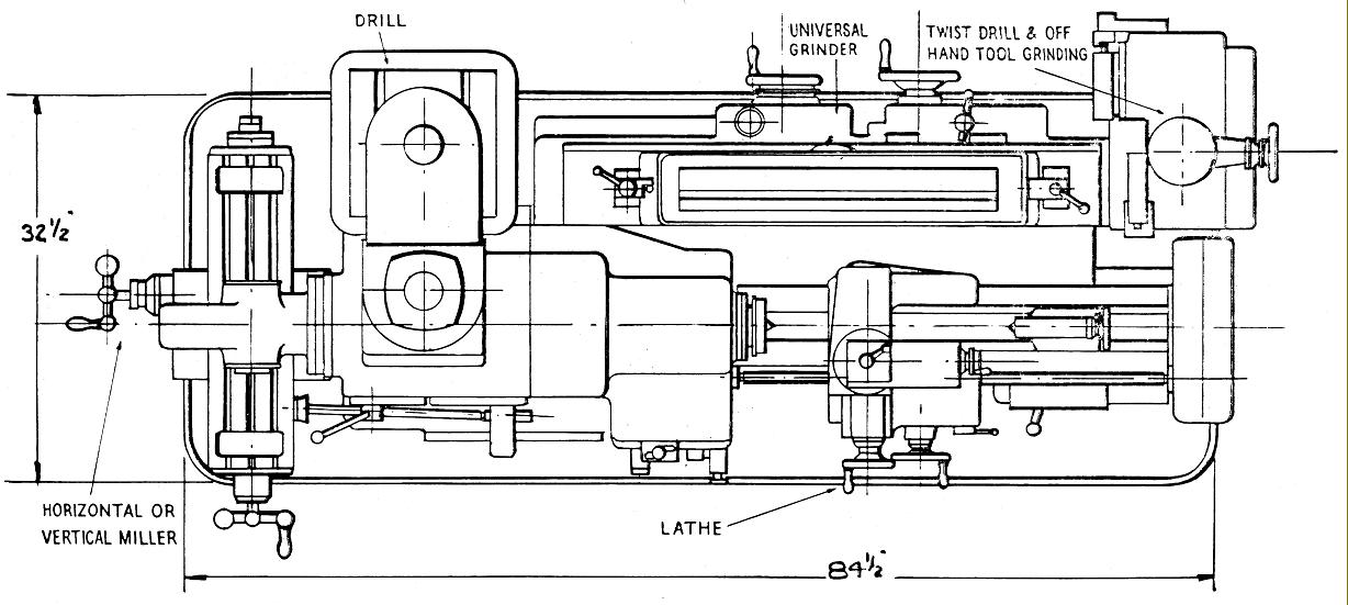
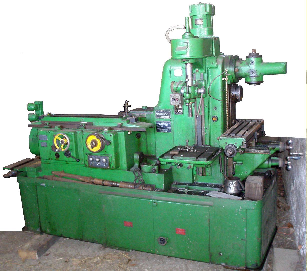
Very much bigger, heavier and more useful than its smaller brother, the larger version of the Universal was 11' 6" long, approximately 3' 8" wide over the handles (with the milling table in its centre position) around 78-inches high and weighed in the region of five tons. The machine combined a sliding, surfacing screwcutting lathe, a universal milling machine, a sensitive drill, a universal grinding machine and a bench grinder with a built-in twist-drill grinding jig. A single 6 h.p. 3-phase motor was used to drive the lathe and universal milling machine with separate motors for the drill and grinder. Although the same motor was used by lathe and miller, their operation was entirely independent, though they did share the same drive gears within the headstock and slipping clutches to protect the feed mechanisms. However, when the grinding machine was in use, this prevented the lathe and miller from being used. Two suds pumps were provided, one for grinder and one for the other three machines. Oil reservoirs were used in abundance - for instance, it appears from an external examination that the feed screws for the milling table each ran in their own oil bath - and the machine was fitted with a pressure oil supply to the main headstock that incorporated a filter. |
|
|
|
|

|
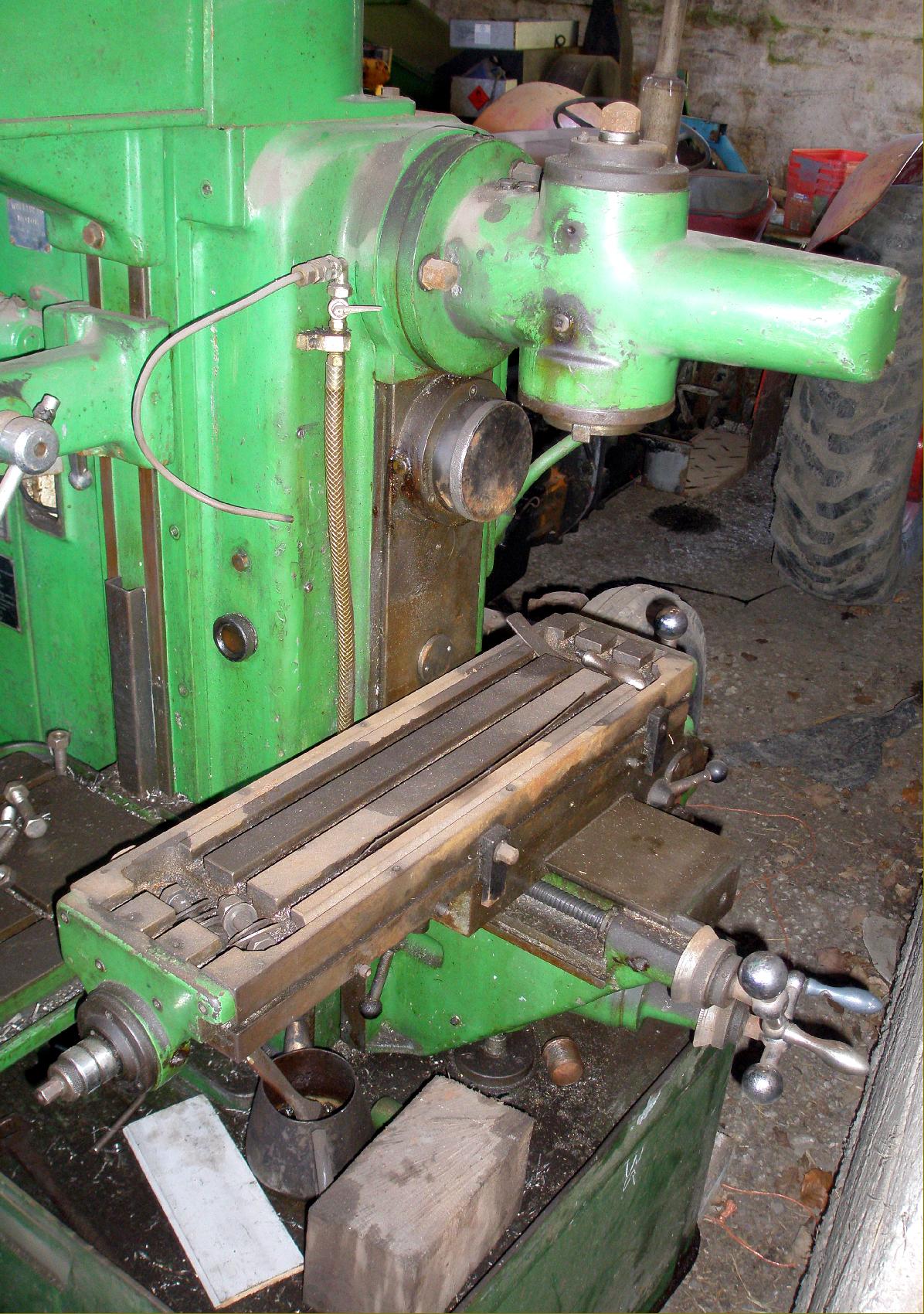
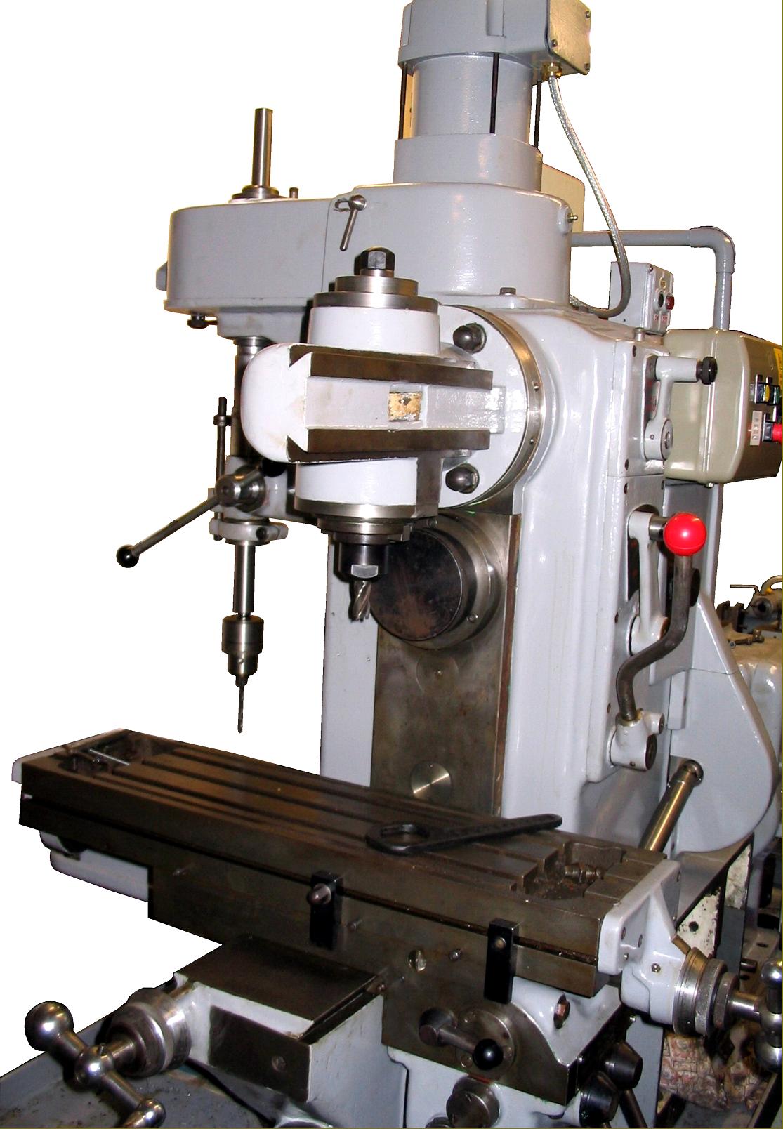
Vertical milling with the head-cum-overarm unit. The geared dividing head, shown playing its part in the production of a helical gear, was on the accessories' list. |
||
|
|
||
|
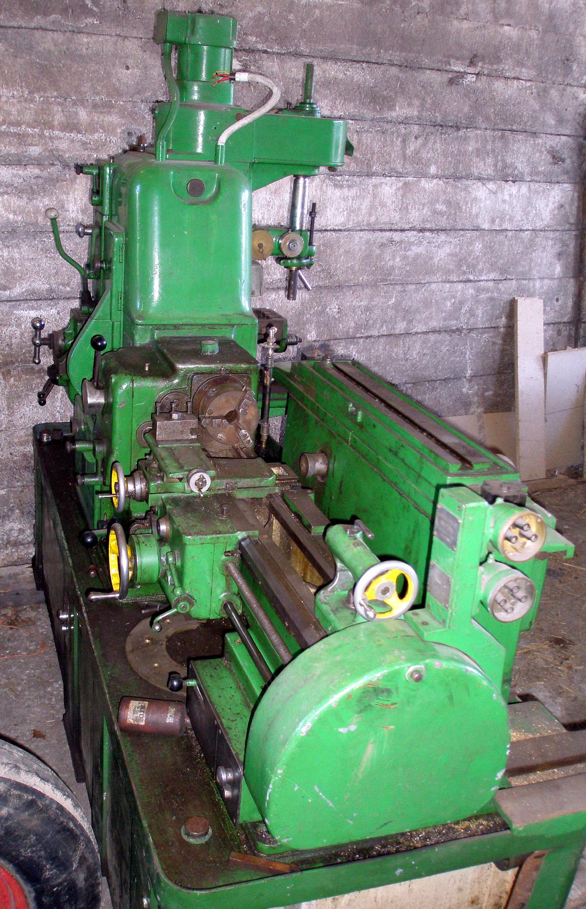
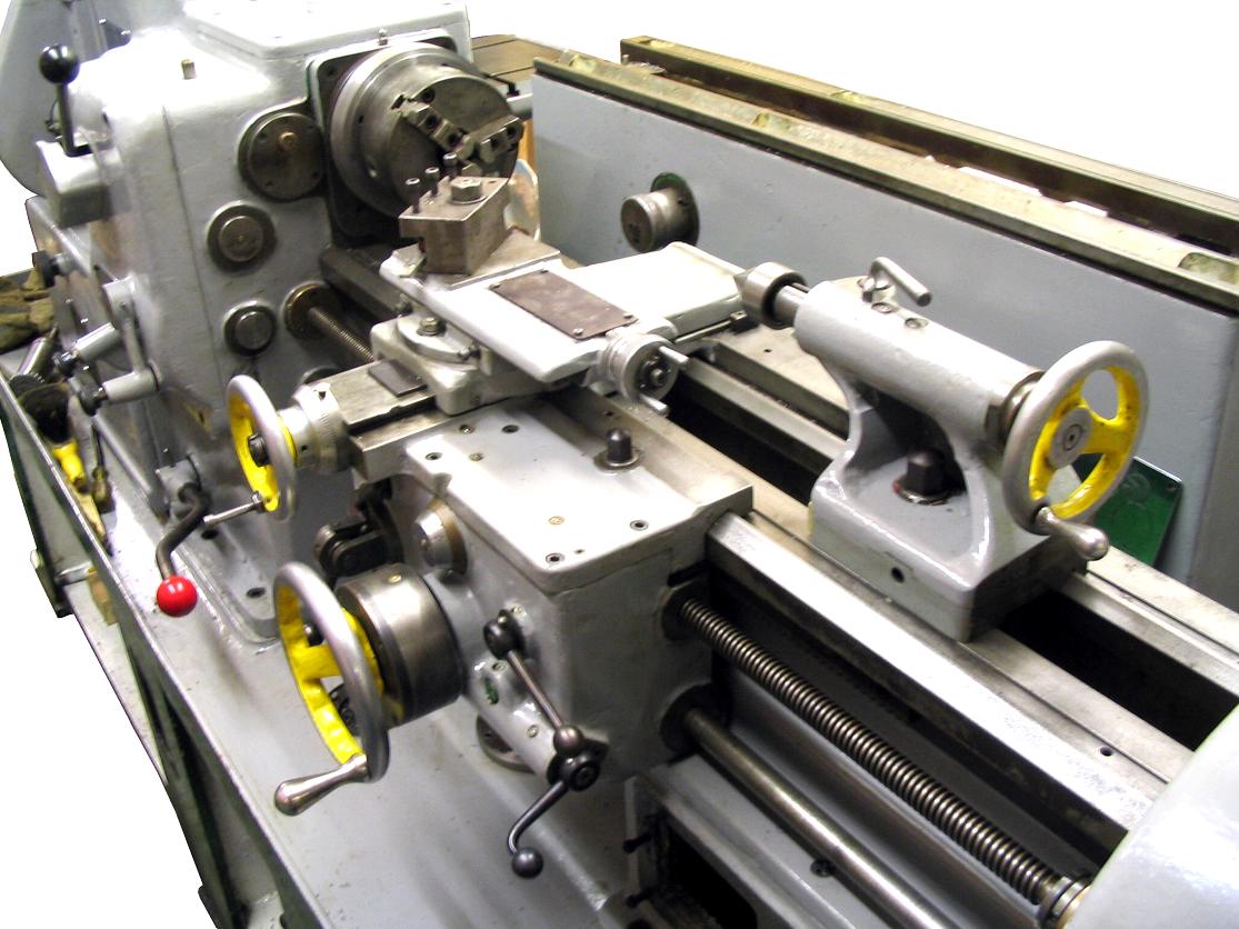
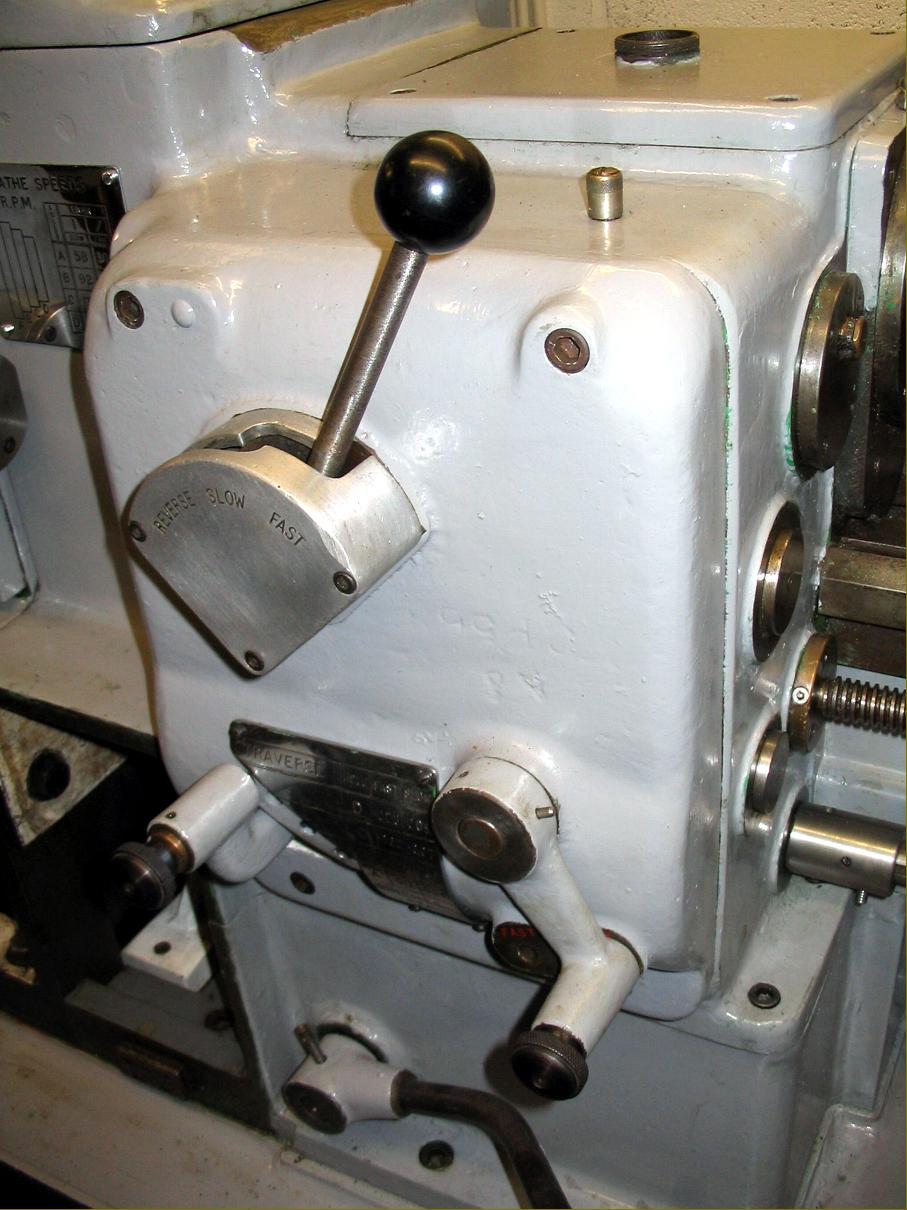
The screwcutting lathe was not large, just an 8" swing by 18" capacity between-centres with 8 speeds of 58, 92, 137, 198, 300, 470, 707 and 1020 rpm. It was driven my a 3 HP 1760 r.p.m. 3-phase motor and had a 0.75" hole through the headstock. |
||
|
|
||
|
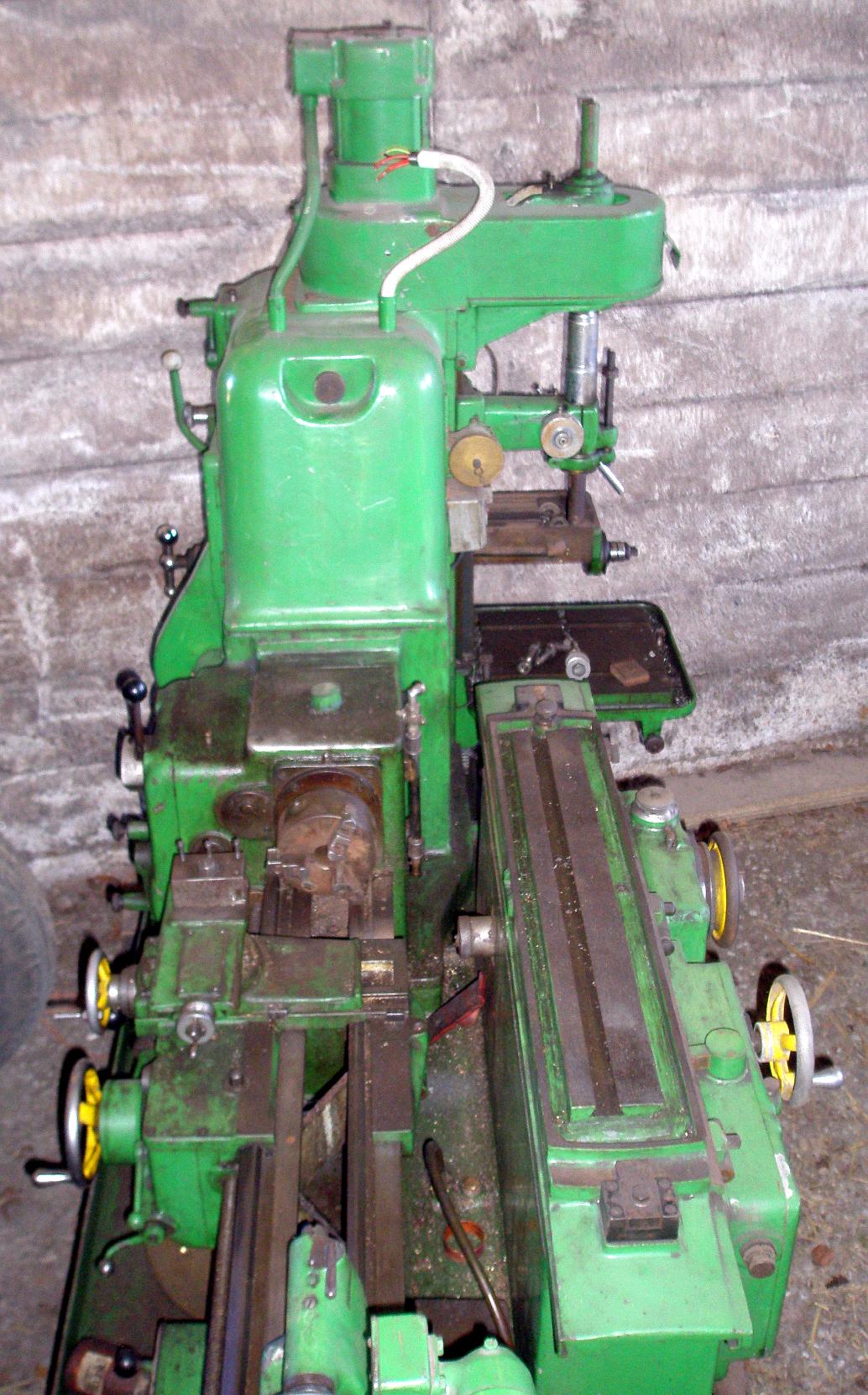
The drill, with a maximum table capacity of 15" in diameter, was mounted at the back of the "headstock" and had six speeds from 420 to 5000 rpm supplied by a 0.5 hp motor. Unfortunately, the quill was fitted with only a No. 1 Morse taper, so severely restricting its capacity for heavy-duty work. |
||
|
The wheel head of the grinding machine normally was stored at the end of the Universal Machine Tool in such a way that it could be used as an off-hand grinder. |
||
|
Universal Grinding |
||
|
|
||
|
|
||
|
Surface grinding was accomplished by mounting a platform on the standard table and attaching a magnetic chuck to it; an extension was also fitted to the standard wheel head to bring the stone forward and so increase its coverage. |
|
|
||
|
The twist-drill grinding attachment being used with the grinding head mounted in its "stored" position on the end of the machine. |
||
|
Adcock & Shipley Horizontal Millers Vertical Millers Machine Tool Manuals Machine Tool Catalogues Belts |
||