|
Continued:
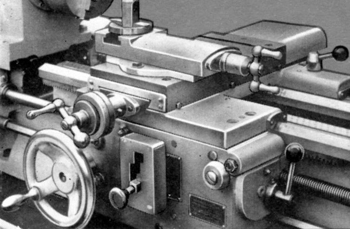
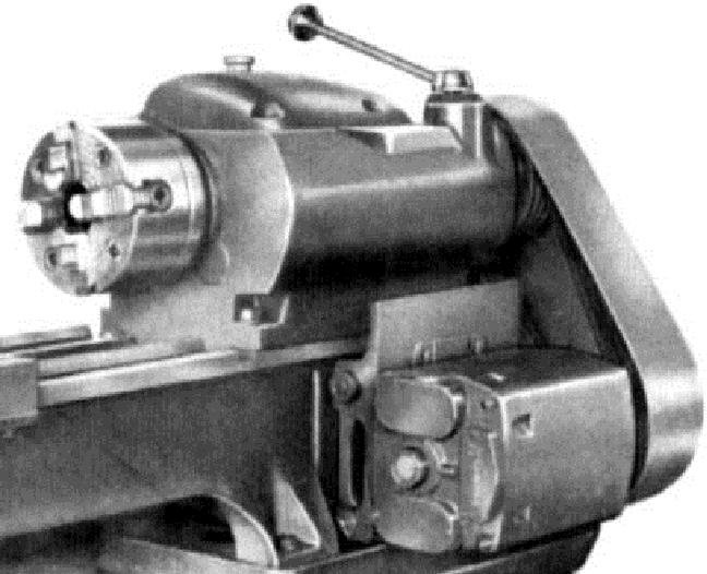
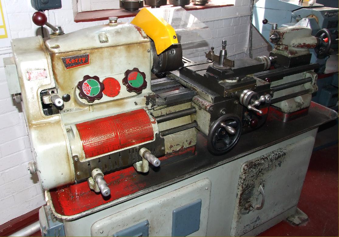
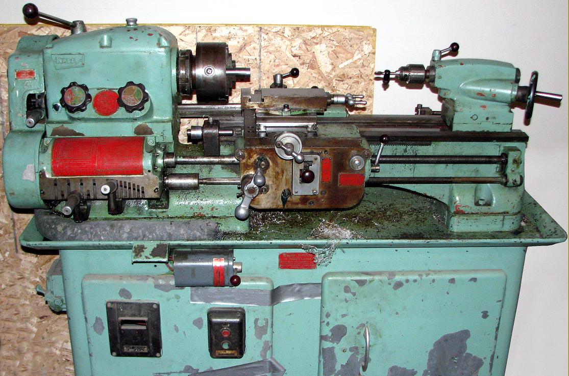
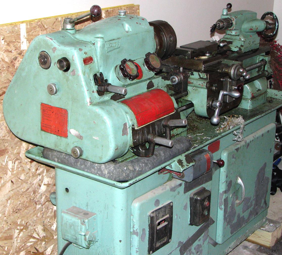
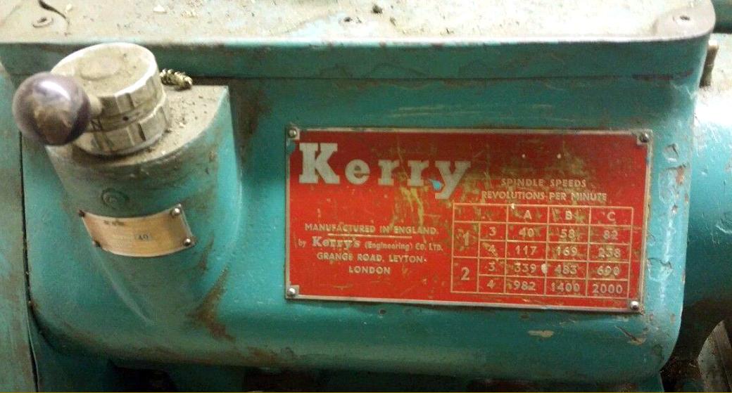
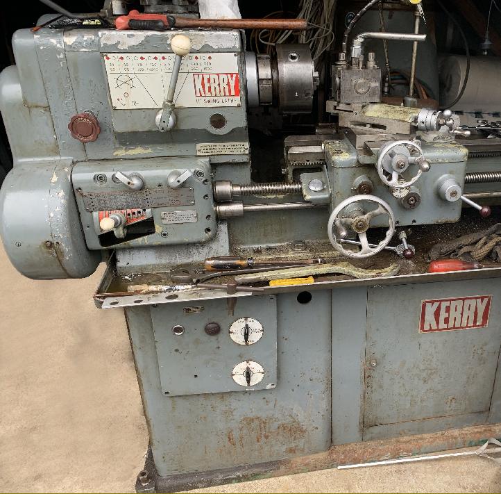
Kerry Mk. 1 A.G. lathe with a single rotary control on the apron to both select and then engage the power sliding and surfacing feeds. The leadscrew clasp nut lever was on the front face of the apron. Note the small headstock spindle speed-control dials
Continued:
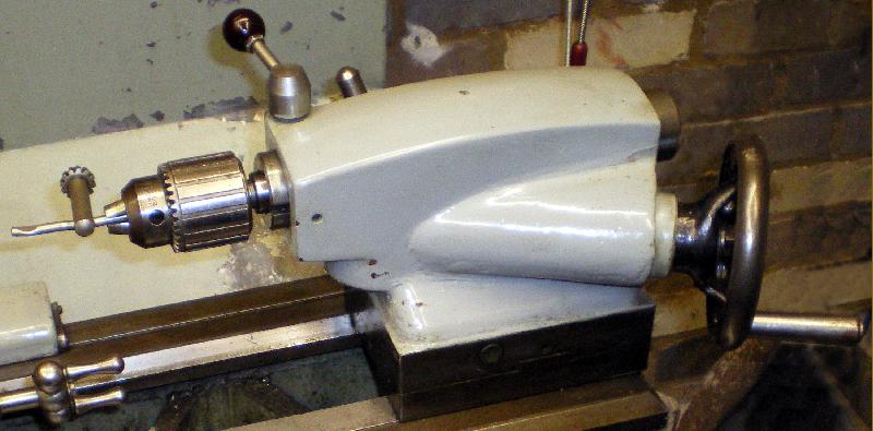
For a 5.5" lathe the bed (for which, at first ,there was no option of a gap) was of massive proportions, heavily ribbed between the walls and carrying a Vee and flat for the saddle and another Vee and flat for the No. 3 Morse taper tailstock - of which some, produced during the late 1950s and 1960s, were fitted with a rack-driven spindle operated through an angled drive with bevel gears.
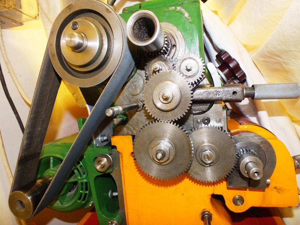
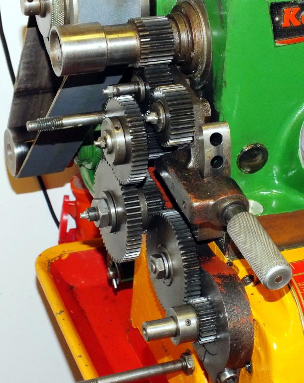
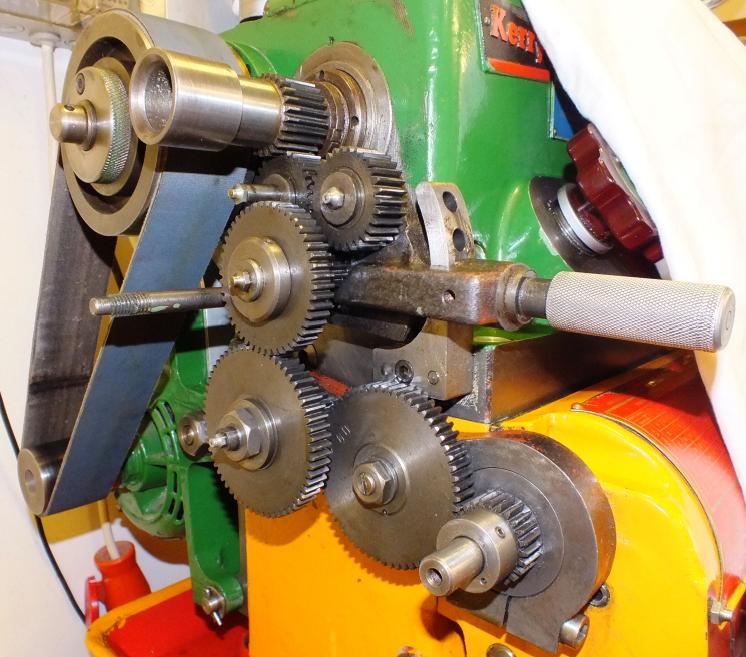
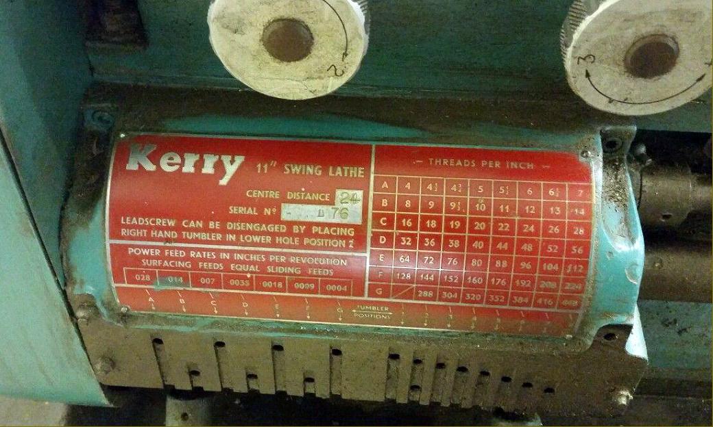
A full screwcutting gearbox, which generated 62 English pitches, was supplied as standard, its changewheel drive from the headstock incorporating a tumble-reverse mechanism. On early lathes the changewheels have been measured as 16DP with a 14.5-degree pressure angle but later examples (reflecting general changes in industry standards) have been found with 18DP gears and a 20-degree pressure angle. Metric threading was also possible, the full range of 60 pitches being obtained by the substitution of three changewheels in the drive train.
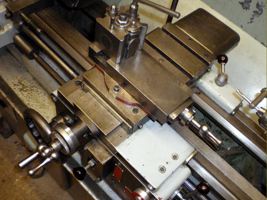
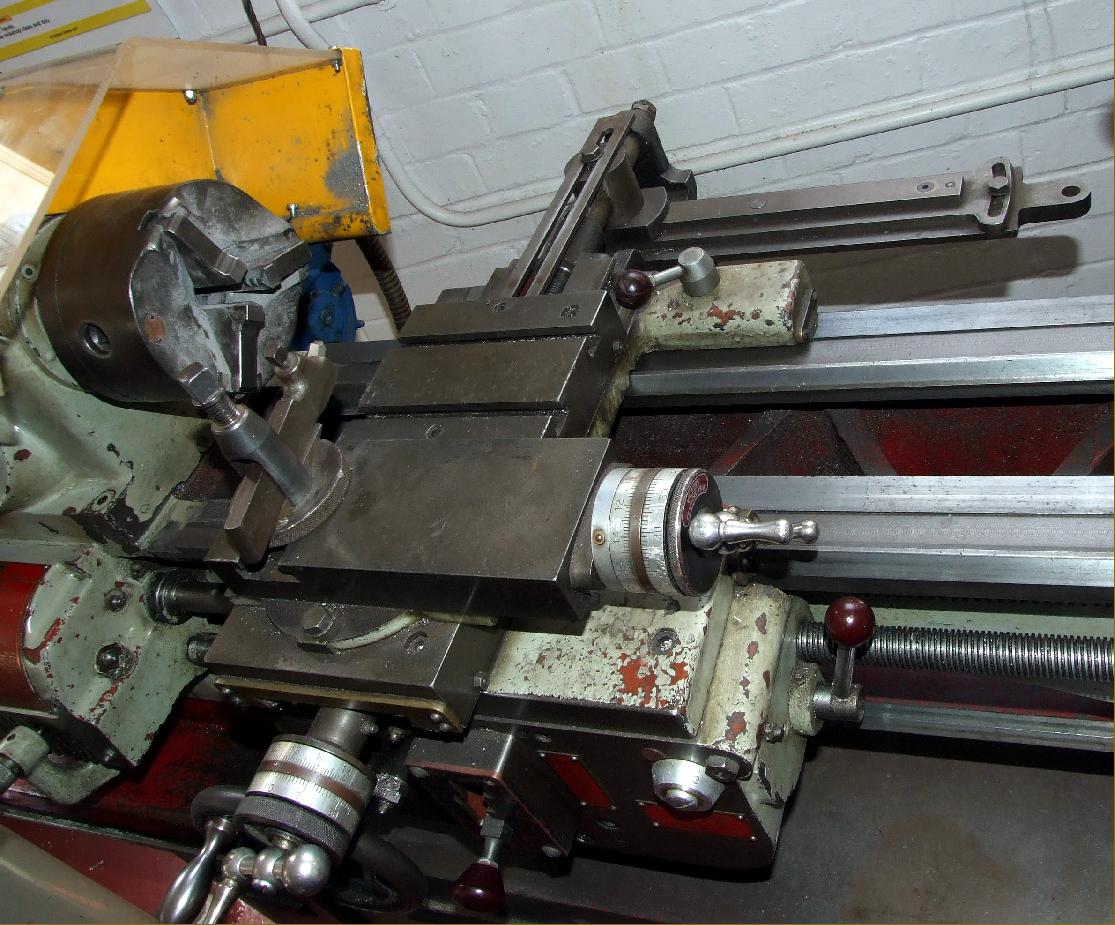
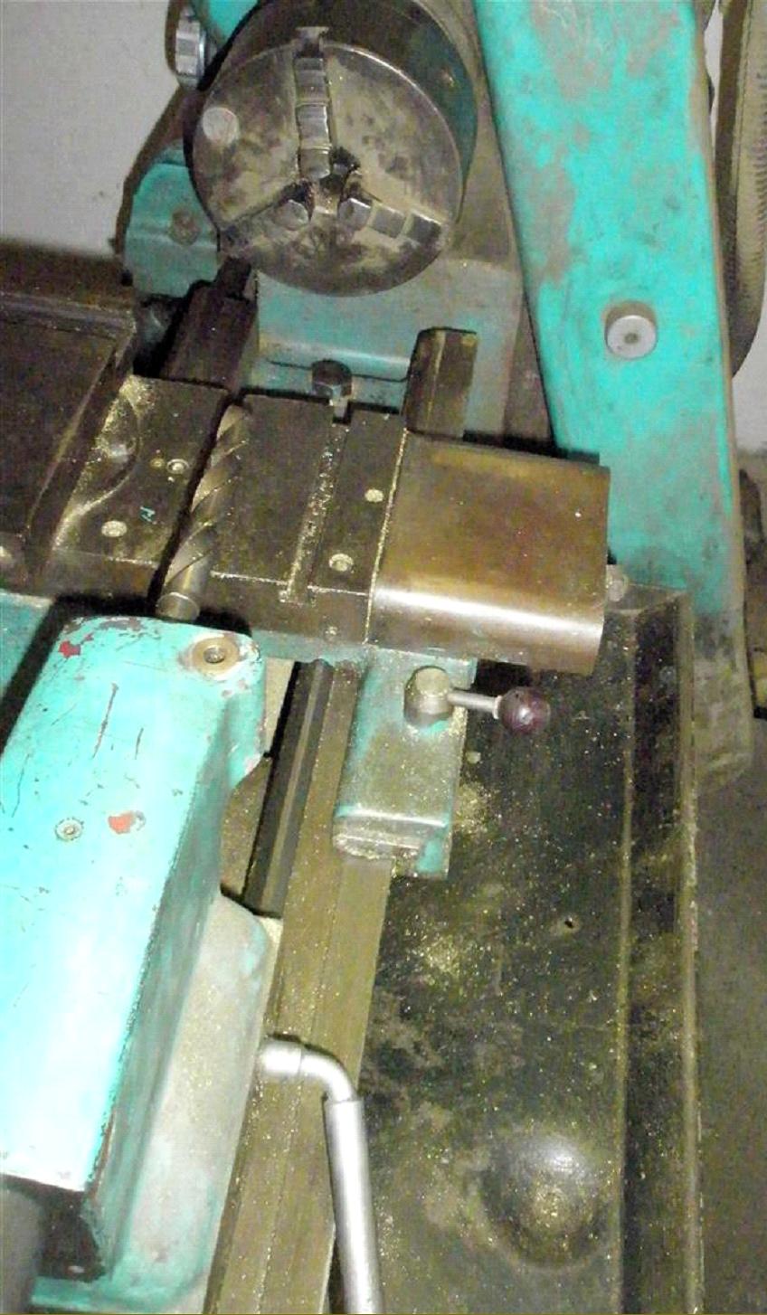
Used only for screwcutting the leadscrew could be disengaged when not in use. A separate power shaft took a drive from the gearbox to the apron where the power sliding and surfacing feeds were (on all but early machines) selected and engaged by just a single lever flicked easily and conveniently though a vertical "gate"; interestingly, this design was copied and used by Taiwanese manufacturers on certain of their 6" centre-height lathes as well as a development of it by Emco on their well-known V10 and V10P machines. Sliding power feeds ranged, in geometrical progression, from a low of 0.000375" to high of 0.24" of carriage travel per single revolution of the spindle. The compound slide rest was especially well built and the wide cross slide equipped with useful T slots. Of course, at first, the micrometer dials were far too small but once the Mk. 2 was in production the size of the cross-feed dial was substantially increased.
The Kerry lathe appears to have been built in four distinct forms: the early, very rare and quite different belt-drive Model D.B, the popular Model A.G. (in what, for convenience if unofficial reference, we shall call the Mk. 1, Mk. 2, Mk. 3 and Mk. 4 forms) and what might be described as the Mk. 5 , the widely-exported Models 1124 and 1140. While all versions of the AG were similar and based directly on the Mk. 1 (but with modified aprons and tailstocks), the 1100/1200-series was extensively redesigned, looked very much more modern and was available in both 11" and 13" versions.
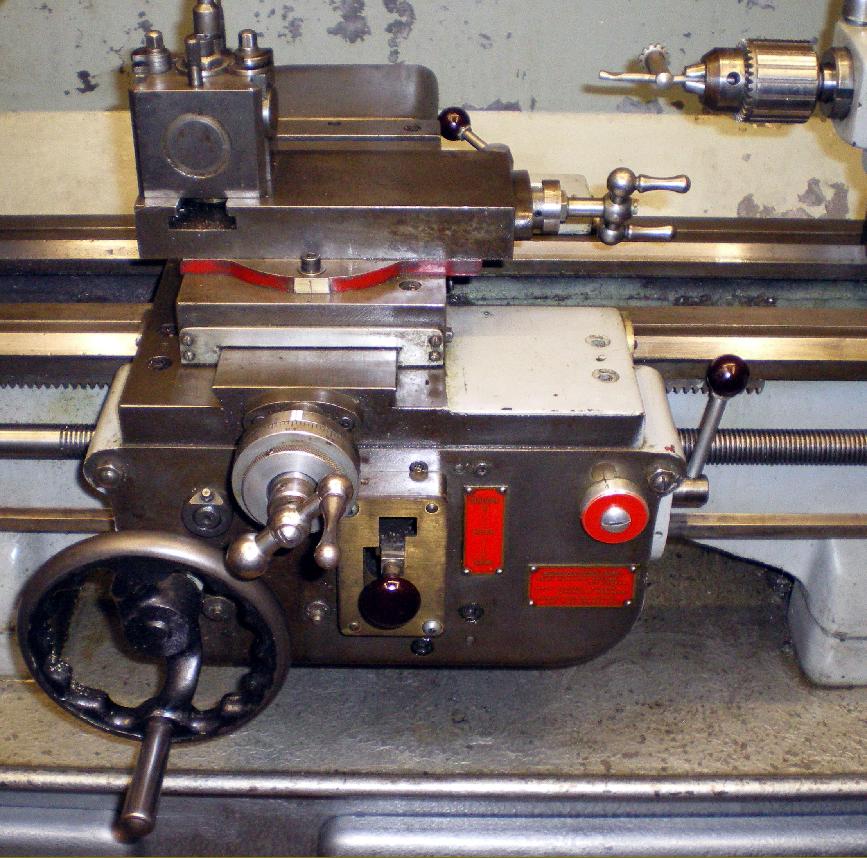
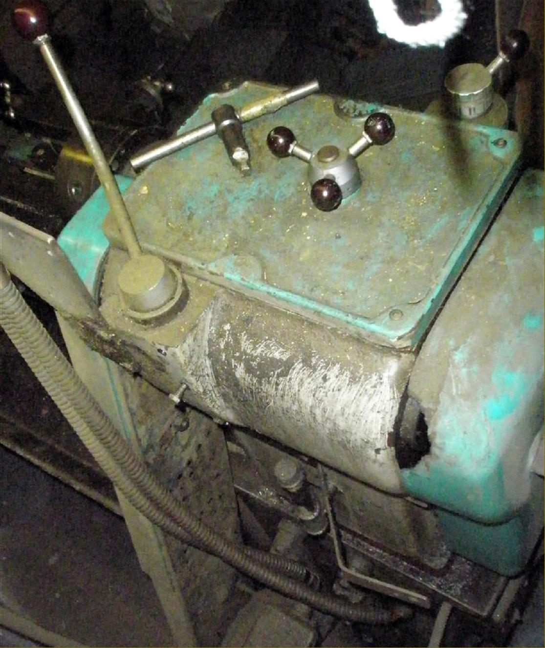
Although they shared many parts the main difference between the three AG lathes was the apron - this item obviously being a point of some difficulty for the Kerry design department who seemed determined that both selection and engagement of the power sliding and surfacing feeds would required only one easy-to-move control instead of the usual two. Their first effort, on the Mk. 1, saw a rotary dial positioned in the front left-hand corner of the apron with the leadscrew clasp nuts operated by a lever in the bottom right-hand corner and the carriage handwheel placed high up and to the right. On the Mk. 2 (a lathe that has sometimes, along with the Mk. 3 been found badged as either the "G.C." or "A.C.") the dial was replaced by a lever moving vertically in a slot cut into the centre face of the apron, with the clasp nuts operated by a lever fixed to the apron's right-hand face. It is not known what problems the first two designs encountered (though the power-feed lever had a horrible feel) but to what must have been the department's great relief the final Mk. 3 apron proved entirely successful. This version, which used a lever moving vertically, then sideways through a dog-leg gate, allowed either sliding or surfacing feeds to be instantly selected and then positively engaged. Very early versions of the Mk. 3 can be identified by the lack of the Kerry logo and absence of a power-feed safety overload clutch. One final, rather odd type has recently (2014) come to light - what we will call, for convenience, the Mk. 4 version of the "A.G., A.C. and G.C." Series. What was written on the maker's identification plate is unknown but the lathe had a very different headstock casting with a 3-spoke handle on the top and a second lever mounted on the front face on the top of a cast-in boss. The speed range was marked as being a very useful 40 to 2000 r.p.m. If you have a Kerry like this the writer would be interested to hear from you.
A weak point on early Kerry lathes was the operating mechanism of the spindle cone-clutch (the clutch itself was fine) with its effectiveness deteriorating over time. Although the clutch mechanism might have changed or been modified on later models, on many examples the fault can be corrected by modifying the arrangement to limit end float in the assembly. At the front the shaft ran in a ball bearing retained by what amounted to a motor-car cylinder block core plug; after time, the plug tended to loosen, allowing the bearing, complete with shaft and clutch, to float from side. Although the float was limited internally by other constraints, the 1/8" play generated was sufficient to cause problems. The cure is to replace the core plug with a top-hat section, bolt-on cap, arranged so that when it fits into the bore it holds the bearing tight against the rear flange. A cap made from aluminium, and held by 3 1/4" bolts is sufficient. However, as a temporary repair, the clutch can be locked up by the twist of an Allen key, so the fault did not need to spoil what was otherwise an excellent lathe.
If the markings are missing from the headstock speed-selector dials - take care, it is possible to rotate them into positions where they can interlock. To check this remove the headstock cover, turn the spindle by hand and watch what happens when you rotate the dials; it should be immediately obvious how their positions relate to the spindle speeds - and a dab of paint can be used to mark their positions.
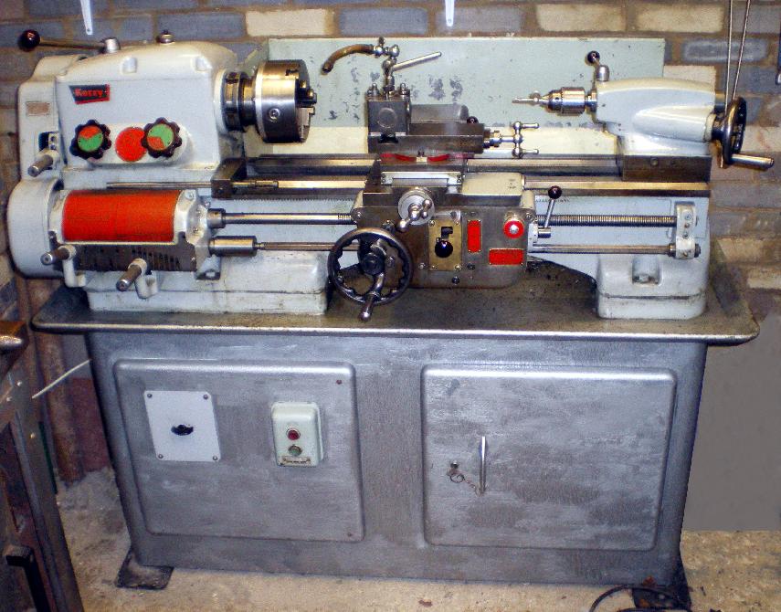
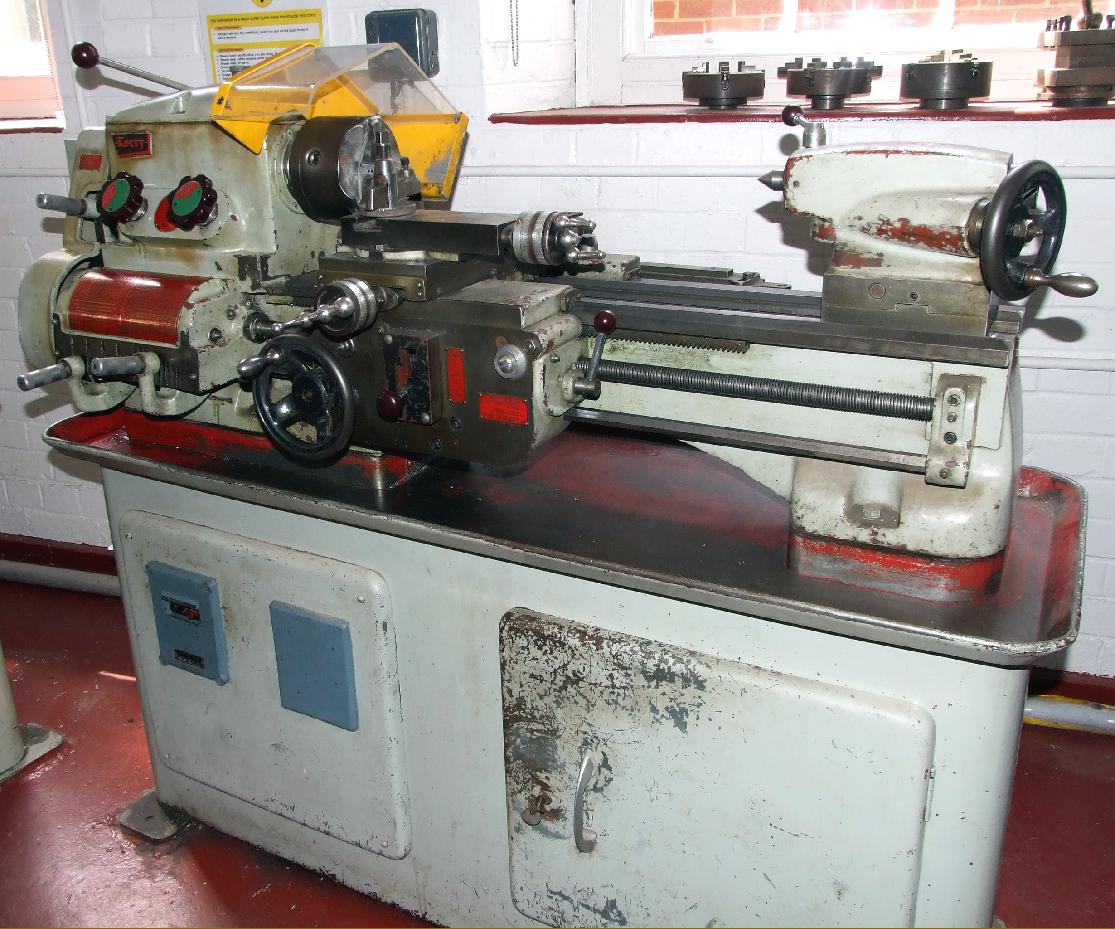
Although available for bench mounting, the Kerry is more often found fitted to the maker's heavy sheet-metal stand with a central drawer that could be locked, a storage locker on the left and, unaccountably - and dangerously out of reach - the electrical switchgear on the right-hand cabinet face. If you find a Kerry like this, before using it move the switchgear to a position where it can be more easily operated. Some lathes are found fitted to a very heavy cast-iron stand and, while this was only ever shown in the adverting literature as being for the rare GC "toolroom" models, several examples of the ordinary lathe been discovered fitted to them as well.
The basic lathe for bench mounting weighed 574 lbs (260 kg). or 802 lbs (364 kg) complete on the sheet-metal cabinet stand.
Supplied with the lathe when new were: an American pattern toolpost, 10" faceplate, chuck backplate, fixed and travelling steadies, three changewheels for metric threading, two Morse taper centres and the necessary spanners and an operation manual..
|
|