 |
|
|
|
|
|
|
|
|
|
|
|
|
|
|
|
|
|
|
|
|
|
|
|
|
|
|
|
|
|
|
|
|
|
|
|
|
|
|
|
|
|
|
|
|
|
|
|
|
|
|
|
|
|
|
|
|
|
|
|
|
|
|
|
|
|
|
|
|
|
|
|
|
|
|
|
|
|
|
|
|
|
|
|
|
|
|
|
|
|
|
|
|
|
|
|
|
|
|
|
|
|
|
|
|
|
|
|
|
|
|
|
|
|
|
|
|
|
|
|
|
|
|
|
|
|
|
|
|
|
|
|
|
|
|
|
|
|
|
|
|
|
|
|
|
|
|
|
|
|
|
|
|
|
|
|
|
|
|
|
|
|
|
|
|
|
|
|
|
|
|
|
|
|
Manufactured from the mid 1930s - and disappearing from the catalogues by the late 1940s - CVA precision miniature lathes were built in three forms: the bench and stand-mounting Models 69, 70, 71 and 72 intended as production capstan lathes (oddly, the catalogues referred to these with two sets of model designations, later editions listing them as the Types 89, 90, 91 and 92); a dedicated second-operation model intended for bench mounting (with no maker's Type designation) and the interesting and unusual Model 75 capstan on an integral, cast-iron cabinet stand.
Although not offered with so wide a range of accessories as the similar Swiss Mikron types, the 3.5-inch centre height CVA Models 89, 90, 91 and 92 nonetheless provided the small machine shop with a high-class lathe adaptable to one-off work and, by mounting thread-chasing headstocks, capstan heads and cut-off slides, the production of small runs of high-precision components. Each part was (like a Mikron or Schaublin) jig made and so accurate that items such as headstocks and slide rests could be transferred from one machine to another with absolute confidence that they would align perfectly.
Each lathe in the series differed only in regards to its drive system - the Model 69 (89) being a bench type supplied without a countershaft; the Model 70 (90) a fully-motorised bench machine incorporating the highly effective and compact "H"-Gear variable-speed unit; the Model 71 (91) a stand-mounted version for connection to the customers own countershaft and the Model 72 (92) being identical to the 71 (91) but fitted with the same built-on drive as offered on the Model 70 (90).
Formed with an integral chip tray and coolant tank, the cast-iron bed was 36" long with the machined locating surfaces occupying some 341/2". The usual type of flat top with bevelled edges was used, the headstock and other attachments being secured by round-head bolts in a central T-slot.
Three headstocks were offered, each with plain bronze bearings and a hardened spindle: the No. 100 as bored through 11/16" and able to accept collets with a through capacity of 5/8". The 4-step cone pulley had diameters of 21/4", 3", 33/4" and 41/2" (with the largest pulley flange equipped with a ring of 8 indexing holes) a lever-action collet closer was supplied as standard and the spindle nose threaded to accept chucks, and faceplates, etc. The Type No. 101 was identical to the type 100 except for a built-in thread-chasing attachment with hobs 13/8" long and the ratio between hob pitch and work 2 : 1. The headstock No. 102 was similar to the Type 100, but intended for much heavier duty work and able to take bar stock up to 1-inch in diameter. Just two pulleys were fitted, each 15/8" wide and the spindle nose - lacking a thread - intended for collet use only. Early models had the headstock left open while later versions had the assembly stiffened by the incorporation of a large cast-in cover that doubled as a perfunctory belt guard.
To compliment the three headstock four slide rest were listed: the No. 200 was the maker's standard screw-feed cut-off slide with a very coarse pitch, double-start feed screw and front and back screw-adjustable stops. Three toolholders were provided, one for parting-off work the others to take forming tools. Slide rest 201 was identical in construction and capacity to the No. 200 - but fitted with a lever-feed action. Rest No. 202 was a compound type with lever feed to both cross and top slides - each with the same travel of 35/8". Three adjustable stops were fitted to each motion and the top slide could be swivelled through 15° each way from central. Slide rest No. 203 was not, as it might have appeared, intended as a compound unit for use in precision between-centres work but was described by the makers as being a cut-off slide. However, although the cross-feed screw was of coarse pitch the top-slide screw was of conventional construction and did allow lengths to be turned accurately. Both feed screws ran thorough adjustable bronze nuts and were fitted with micrometer dials graduated in 0.001" divisions
When not supplied without a countershaft, the lathes were equipped with the self-contained "H"-Gear variable-speed drive unit - a mechanism also offered by the Company as an attachment suitable for a wide range of small machine tools (even after manufacture of the precision lathes stopped, the drive continued to be listed for a number of years). In addition to the clever variable-speed gear mechanism, the designers had also considered the thorny problem of belt tension--and solved it by the neat means of two adjustable jockey pulleys. With a speed range of 250 to 2500 r.p.m. the unit had a flange-mounted 1500 r.p.m. 0.5 h.p. motor and an integrated turret assembly holding a shaft the shaft by which means the speed could be varied - a long lever reaching towards the operator with the speeds engraved on graduated quadrant plate. Unlike swash-plate designs, the gear-driven CAV unit could select the speed not only when being driven, but also when stationary.
Introduced in the late 1930s, the CVA Precision Capstan Lathe (it lacked a maker's Model designation) was built in early and late versions - the first having its motor mounted externally, the later with it built into the stand with drive to the "H"-gear variable-speed drive unit by twin V-belts. Both versions used a flat-belt final drive to a pulley overhung on the left-hand end of the spindle. Although details of the first version are sketchy, it is known that the later models were very well built an even incorporated a pressure lubrication system to the plain bronze bearing headstock spindle - the latter in nitralloy with a pressure gauge on the front of the headstock. The oil pumps were driven from extensions to the main motor and all neatly enclosed within the cabinet stand.
Introduced in the late 1930s, the Model 75 CVA Precision Capstan Lathe was built in early and late versions - and was always mounted on a very heavy cast-iron cabinet stand with strong internal cross ribs. At first the motor was mounted externally, then later built into the stand with drive to the "H"-gear variable-speed drive unit by twin V-belts. Both versions used a flat-belt final drive to a pulley overhung on the left-hand end of the spindle and had a speed range of 250 to 2500 r.p.m. Although details of the first version are sketchy, it is known that the later models were very well built, and even featured a hardened spindle (in nitralloy) running in force-feed-lubricated bearings with a pressure gauge on the front of the headstock. Both oil and coolant pumps were driven from extensions to the main motor and neatly enclosed within the cabinet stand.
Two headstocks were offered, the No. 100 and 101, both of the same specification but with the latter (as on the maker's other capstan lathes) incorporating a thread-chasing attachment. Three slide rests were listed, the 200 with a single screw-operated cut-off feed, the 201 with lever feed and the 203 with screw-feed and micrometer dials.
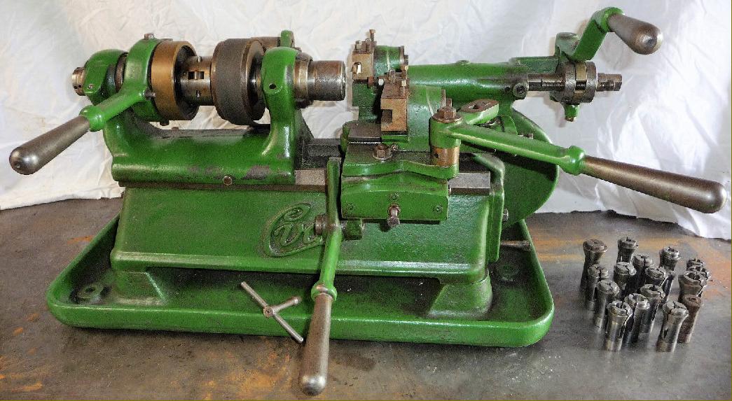
Known to have been manufactured during WW2, the CVA second-operation lathe (it too lacked a Model Type designation) was designed for small batch work. With a 315/16" centre height, the machine could be supplied for drive by the customer's own countershaft or with a neat, built-on drive system. When supplied in the latter form a 2-speed, 1500/3000 r.p.m. 3/4 h.p. 3-phase motor
|
|
|
|
|
|
|
|
|
|
|
|
|
|
 |
|
|
|
|
|
|
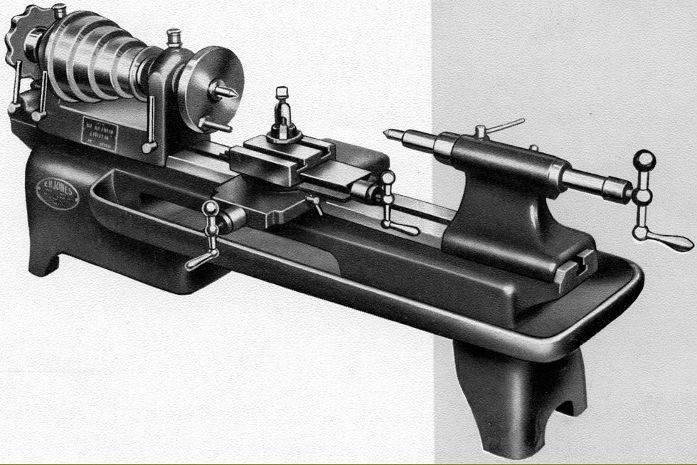
Basic machine of the Series - the Model 69 (89) a bench lathe supplied without a drive system
|
|
|
|
|
|
|
 |
|
|
|
|
|
|
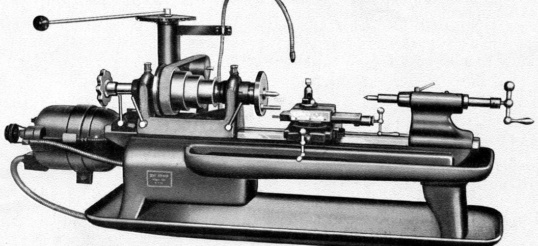
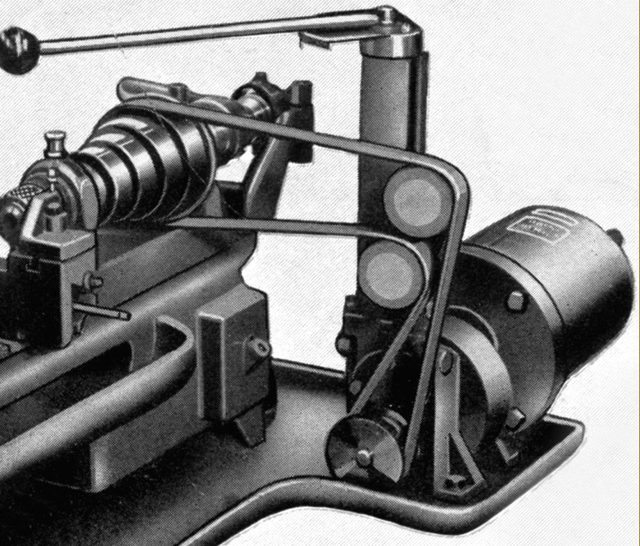
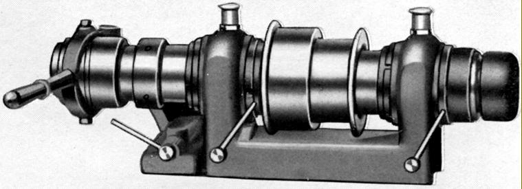
Model 70 for bench mounting with a built-on countershaft /motor system including the highly effective and compact "H"-Gear variable-speed drive unit. The lathe shown is fitted with a No. 100 headstock and No. 203 slide-rest assembly
|
|
|
|
|
|
|
 |
|
|
|
|
|
|
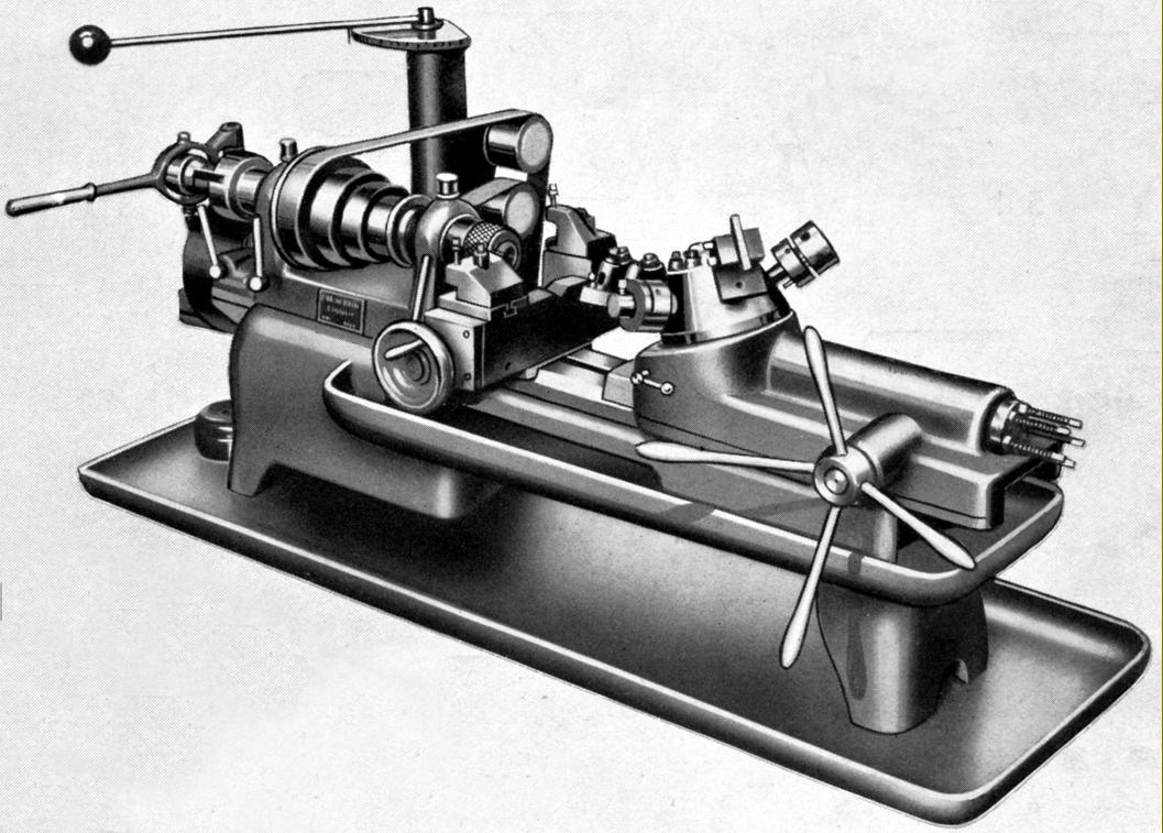
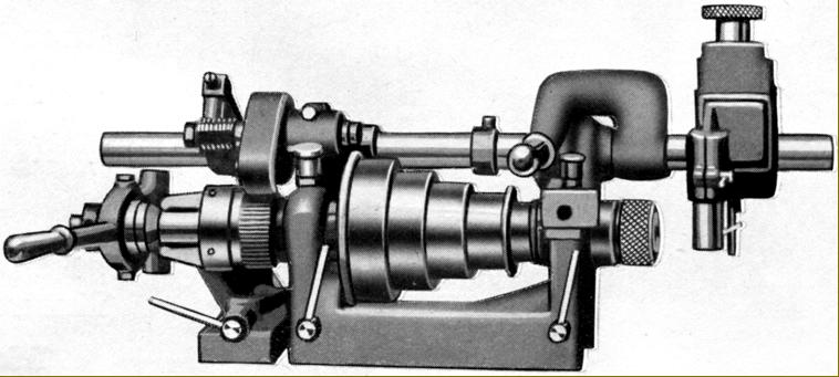
Model 70 for bench mounting equipped for batch production work with a No. 100 headstock, a 5-station turret head able to accept tooling with a shank diameter of 5/8" and a No. 200 screw-feed cut-off slide.
|
|
|
|
|
|
|
|
|
|
|
|
 |
|
|
|
|
|
|
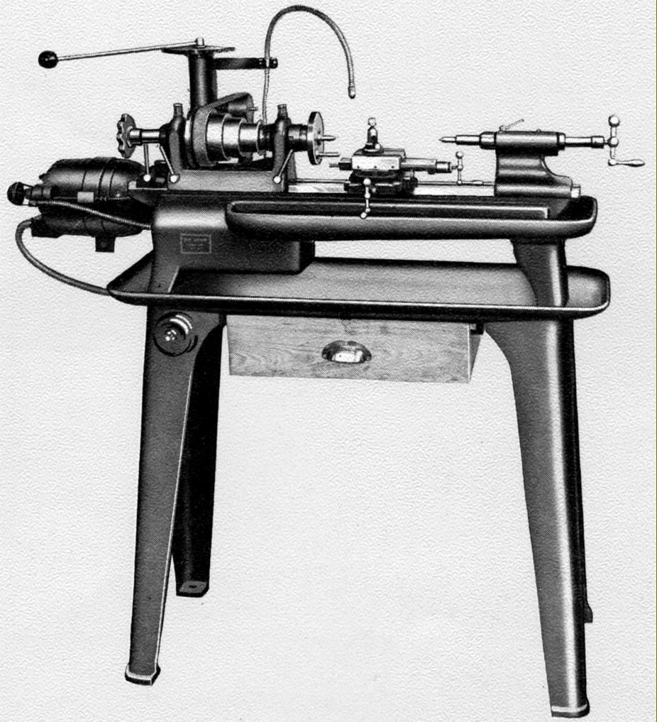
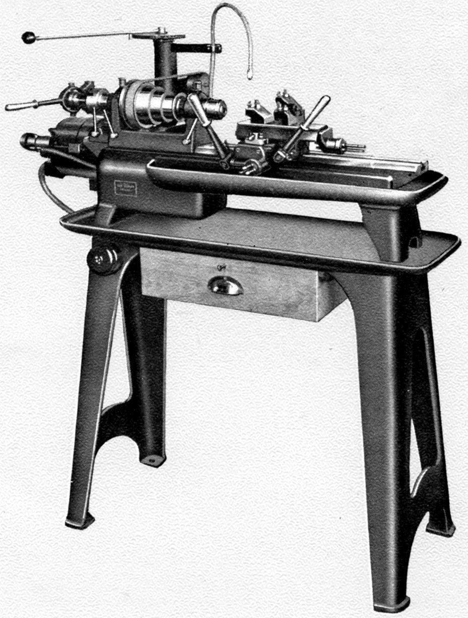
Model 72 (92) a floor-stand mounted version with a built-on countershaft /motor system incorporating the "H"-Gear variable-speed drive unit. The lathe shown is fitted with a No. 100 headstock and No. 203 slide-rest assembly
|
|
|
|
|
|
|
 |
|
|
|
|
|
|
Another variation on the Model 72 (92) fitted with a No. 100 headstock and the No. 202 slide rest.
|
|
|
|
|
|
|
|
|
|
|
|
 |
|
|
|
|
|
|
A later version of the Model 72 (92) with a headstock stiffened by a large enclosure over its front face
|
|
|
|
|
|
|
 |
|
|
|
|
|
|
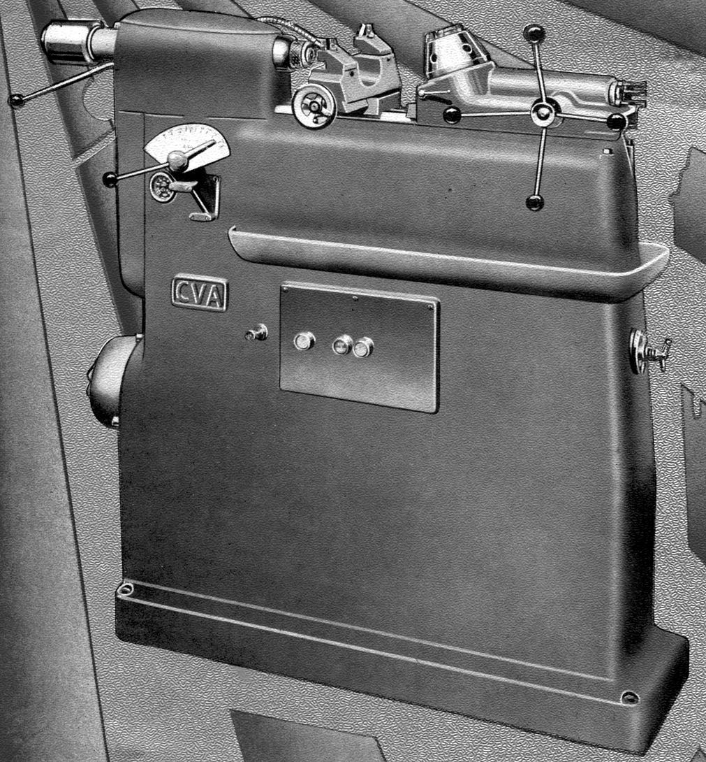
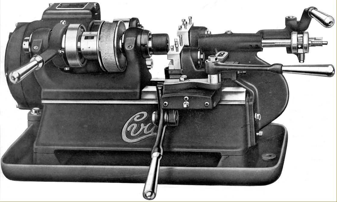
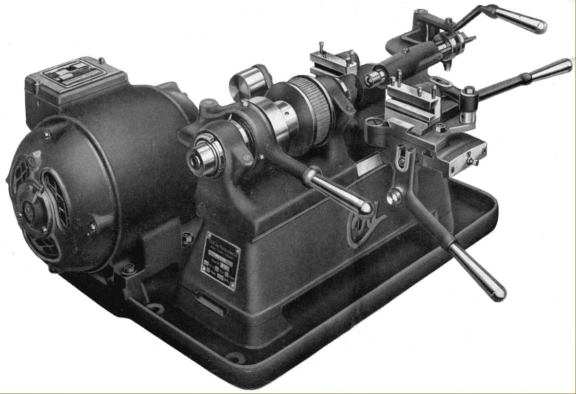
Introduced in the late 1930s, the CVA Model 75 Precision Capstan Lathe was built in early and late versions - and was always mounted on a very heavy cast-iron cabinet stand with strong internal cross ribs. At first the motor was mounted externally, then later built into the stand with drive to the "H"-gear variable-speed drive unit by twin V-belts. Both versions used a flat-belt final drive to a pulley, overhung on the left-hand end of the spindle, the assembly having a speed range of 250 to 2500 r.p.m. Although details of the first version are sketchy, it is known that the later models were very well built, and even featured a hardened spindle (in nitralloy) running in force-feed-lubricated bearings with a pressure gauge on the front of the headstock. Both oil and coolant pumps were driven from extensions to the main motor and neatly enclosed within the cabinet stand.
|
|
|
|
|
|
|
 |
|
|
|
|
|
|
|
|
|
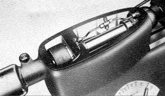
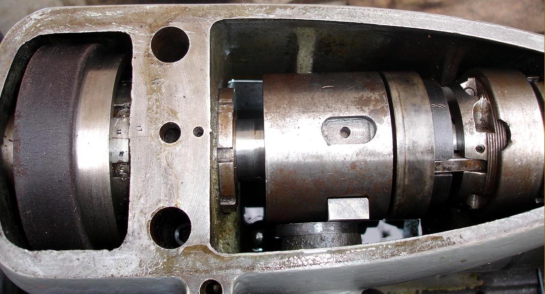
Inside the headstock of the CVA precision capstan lathe
|
|
|
|
|
|
|
|
|
|
|
|
 |
|
|
|
|
|
|
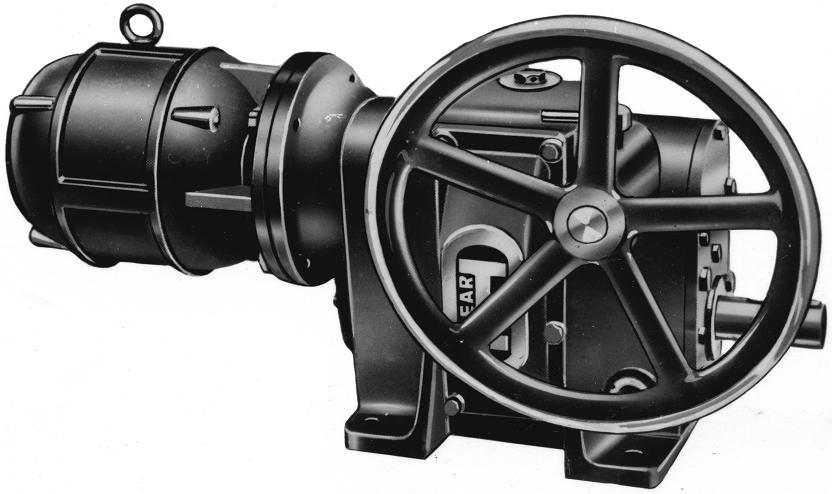
Mounting of the "H"-Gear drive unit. With a speed range of 250 to 2500 r.p.m. the CAV variable-speed drive unit had a flange-mounted 1500 r.p.m. 0.5 h.p. motor. An integrated turret assembly held the shaft by which means the speed could be varied - a long lever reaching towards the operator with the speeds engraved on graduated quadrant plate. Unlike swash-plate designs, the gear-driven CAV unit could select the speed not only when being driven but also when stationary.
|
|
|
|
|
|
|
 |
|
|
|
|
|
|
The "H"-Gear unit was not just fitted to CVA lathes, but also offered by the Company as an attachment suitable for a wide range of small machine tools - and even after manufacture of the precision lathes stopped, the drive continued to be listed for a number of years. In addition to the clever variable-speed gear mechanism the designers had also considered the thorny problem of belt tension--and solved it by the neat means of two adjustable jockey pulleys.
|
|
|
|
|
|
|
 |
|
|
|
|
|
|
An alternative version of the "H"-Gear drive intended to be built into almost any kind of small plant.
|
|
|
|
|
|
|
|
|
|
|
|
 |
|
|
|
|
|
|
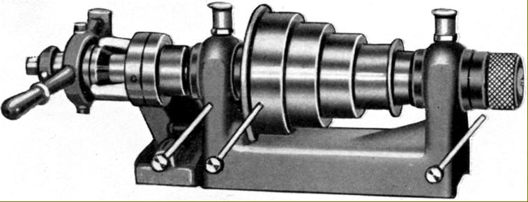
Headstock No. 100. Bored through 11/16" and able to accept collets with a through capacity of 5/8". The 4-step cone pulley had diameters of 21/4", 3", 33/4" and 41/2".A lever-action collet closer was supplied as standard, the largest pulley flange equipped with a ring of 8 indexing holes and the spindle nose threaded to accept chucks, and faceplates, etc.
|
|
|
|
|
|
|
 |
|
|
|
|
|
|
Headstock No. 101. Identical to the type 100 except for a built-in thread-chasing attachment The hobs were 13/8" long and the ratio between hob pitch and work 2 : 1
|
|
|
|
|
|
|
 |
|
|
|
|
|
|
Headstock No. 102. Similar to the Type 100 but intended for much heavier duty work and able to take bar stock up to 1-inch in diameter. The two pulleys were each 15/8" wide and the spindle nose - lacking a thread - intended for collet use only
|
|
|
|
|
|
|
 |
|
 |
|
|
|
|
|
|
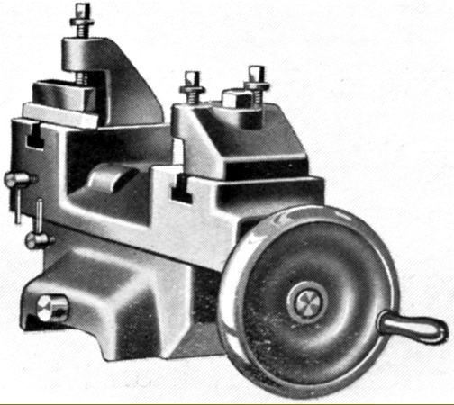
Slide rest No. 200. This was the maker's standard screw-feed cut-off slide with a very coarse pitch, double-start feed screw and front and back screw-adjustable stops. Three toolholders were provided, one for parting off the others to take forming tools
|
|
|
|
|
|
|
|
 |
|
|
|
|
|
|
|
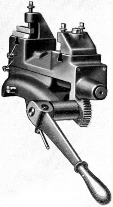
Slide rest 201. Identical in construction and capacity to the No. 200 this was fitted with a lever-feed action
|
|
|
|
|
|
|
|
|
|
|
 |
|
|
Slide rest No. 203. was not, as it might have appeared, intended as a compound unit for use in precision between-centres work but designated by the makers as a cut-off slide and fitted with a coarse-pitch cross-feed screw. However, the top-slide screw was of conventional construction and did allow lengths to be turned accurately
|
|
|
|
|
|
|
|
|
|
|
Slide rest No. 202. A compound slide assembly with lever feed to both cross and top slides - each with the same travel of 35/8". Three adjustable stops were fitted to each motion and the top slide could be swivelled through 15° each way from central
|
|
|
|
|
|
|
|
|
|
|
|
 |
|
|
|
|
|
|
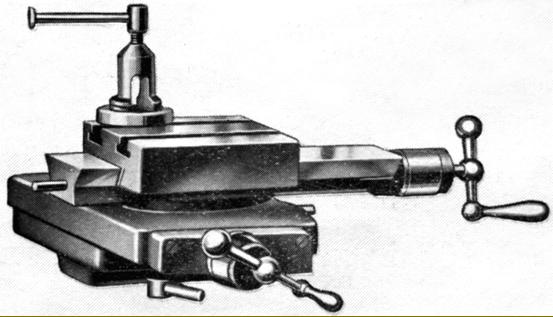
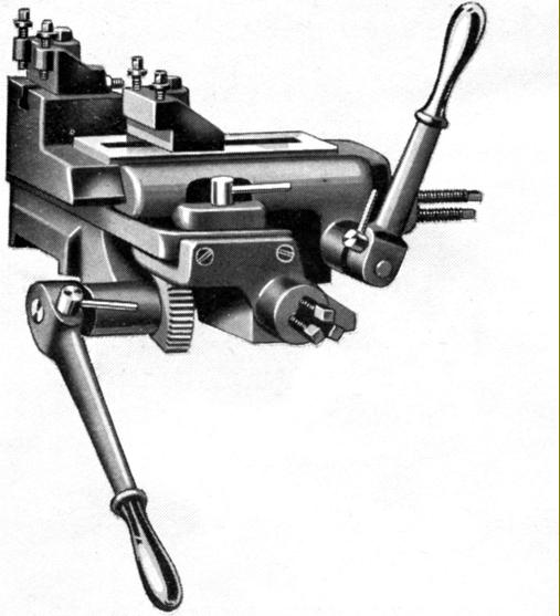
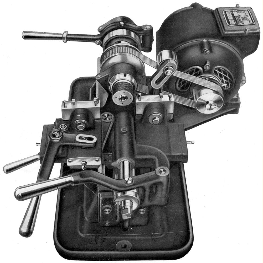
Known to have been manufactured during WW2, the CVA second-operation lathe was designed for small batch work. With a 315/16" centre height, the machine could be supplied for drive by the customer's own countershaft or with a neat, built-on drive system. When supplied in the latter form a 2-speed, 1500/3000 r.p.m. 3/4 h.p. 3-phase motor was fitted as standard that gave two spindle speeds of 1020 and 2010 r.p.m. Bored through 7/16", the hardened spindle ran in adjustable bronze bearings and was fitted with a lever-operated collet closer. The tailstock was bolted in position on the end face of the bed (allowing it to be removed when a self-indexing 5-station capstan head was to be fitted) with a swan-neck casting cantilevering the barrel assembly forwards to leave just 23/4" between centres (with a minimum distance of 3/8"). The lathe was fitted with a compound, lever-operated slide, the cross movement of which was 11/8" and that of the top slide 2". Interestingly, the front and rear toolposts were height-adjustable. Photographs of this lathe type here
|
|
|
|
|
|
|
 |
|
|
|
|
|
|
|
|
 |
|
|
|
|
|
|
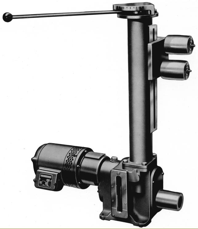
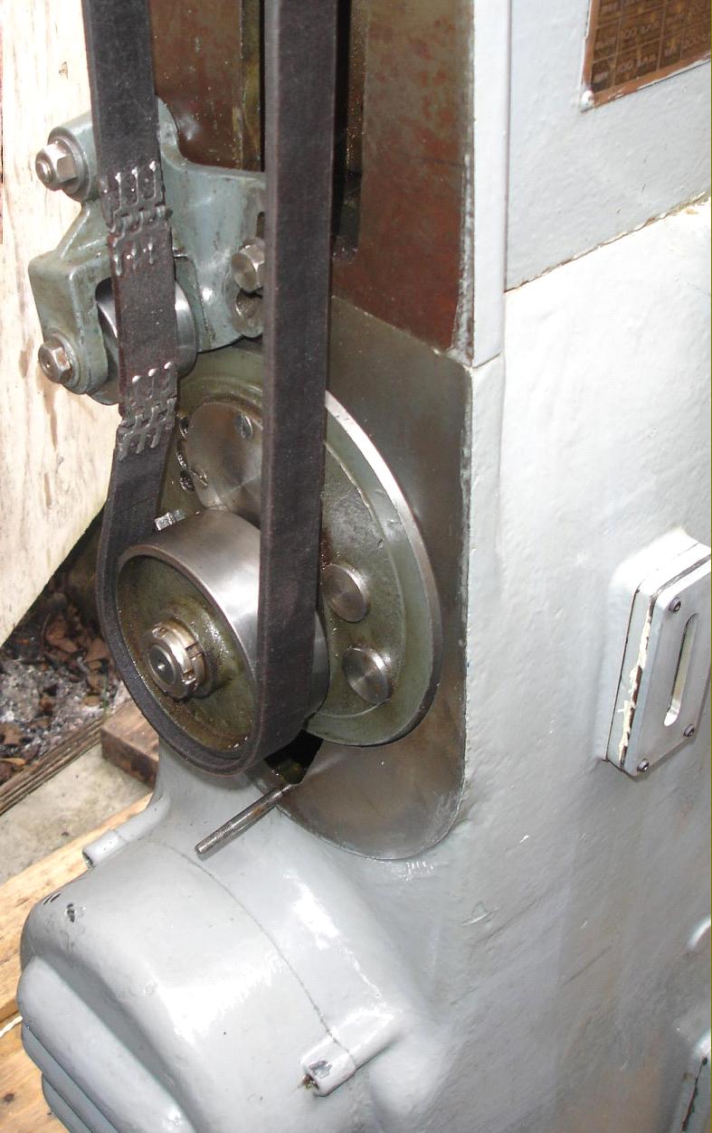
A view of the CVA Second-operation lathe showing the neat jockey-pulley tensioning arrangement for the drive belt
|
|
|
|
|
|
|
 |
|
|
|
|
|
|
|
|
|
|
 |
|
|
|
|
 |
|
|
|
|
|
|
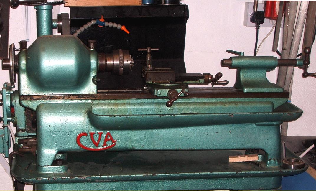
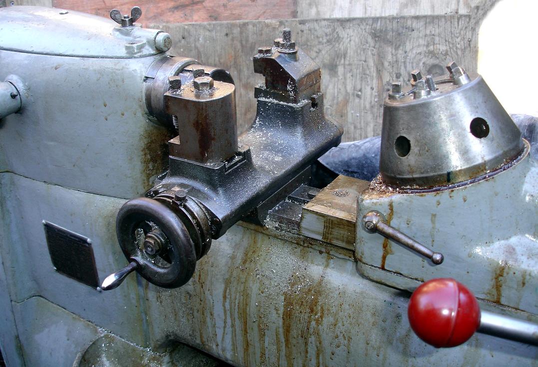
CVA Model 75 Precision Capstan
|
|
|
|
|
|
|
|
|
|
|
|
 |
|
|
|
|
 |
|
|
|
|
 |
|
|
|
|
 |
|
|
|
|
|
|
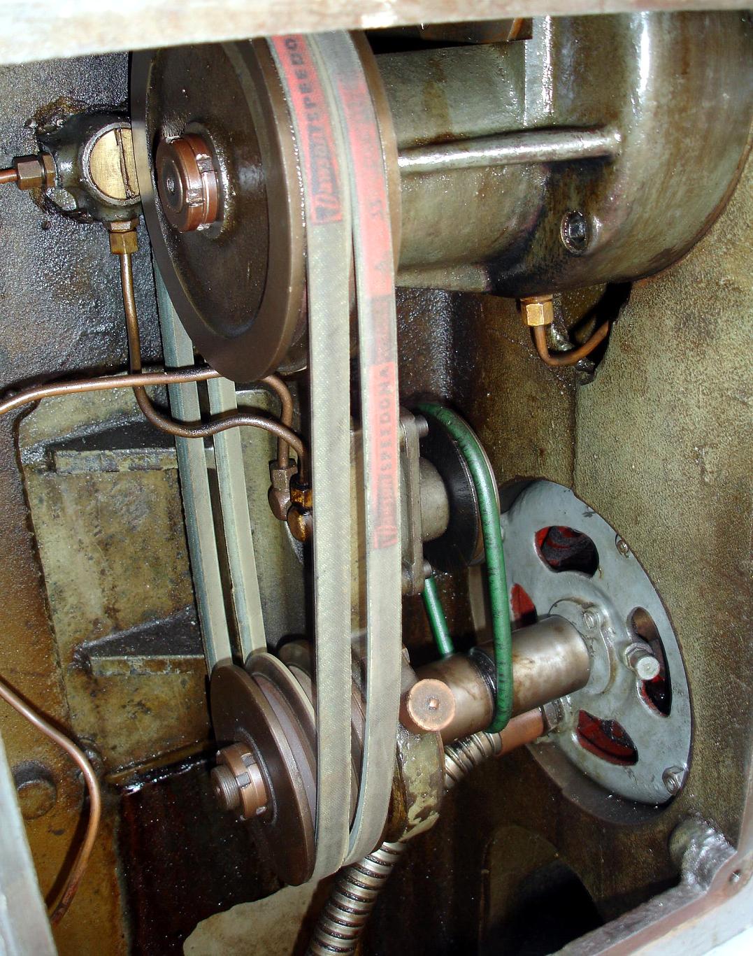
CVA Model 75 Precision Capstan Lathe. Both oil and coolant pumps were driven
from extensions to the main motor and neatly enclosed within the cabinet stand.
|
|
|
|
|
|
|
|
|
|
|
|
|
|
|
|