 |
|
|
|
|
|
|
|
|
|
|
|
|
|
|
|
|
|
|
|
|
|
|
|
|
|
|
|
|
|
|
|
|
|
|
|
|
|
|
|
|
|
|
|
|
|
|
|
|
|
|
|
|
|
|
|
|
|
|
|
|
|
|
|
|
|
|
|
|
|
|
|
|
|
|
|
|
|
|
|
|
|
|
|
|
|
|
|
|
|
|
|
|
|
|
|
|
|
|
|
|
|
|
|
|
|
|
|
|
|
|
|
|
|
|
|
|
|
|
|
|
|
|
|
|
|
|
|
|
|
|
|
|
|
|
|
|
|
|
|
|
|
|
|
|
|
|
|
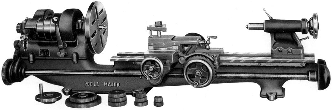
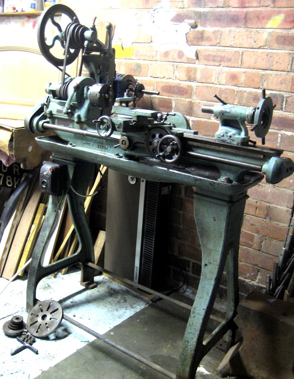
Built along very similar lines to the Company's "Special" - but of heavier construction - the 4" x 20" gap-bed, backgeared and screwcutting Pools "Major" was introduced in 1935. Unusually for its market, it was fitted with cap-type spindle bearings instead of the simpler split kind and offered both power sliding and surfacing from a clutched gear mechanism built into the front and back of the saddle. The power sliding and surfacing arrangement was very much an "add-on" type and of a design that had fallen out of favour on larger lathes by the end of the 19th century. The mechanism used an extension to the tailstock end of the leadscrew that drove a drive a train of gears mounted across the tailstock end of the bed - the gears connecting to a long, overhung "power shaft" mounted parallel with the rear face of the bed. Although fitted with a bearing at just one end, where the shaft passed through a worm-wheel carried on the rear face of the saddle, additional support was provided to the shaft by a bracket also attached to the same casting. The worm-wheel drove a large gear wheel, the shaft of which passed forwards through the saddle to drive a large gear on the front of the apron - this gear meshing in turn with a pinion that drove the carriage along the bed by engaging with the normal hand-feed rack. The large driven gear at the back of the bed (72t) also engaged with a smaller gear (18t) fastened directly to the end of the cross-feed screw - thus providing an automatic surfacing feed. The mechanism was engaged by the simple means of screw-in knobs forcing the gears into a taper at the end of their respective shafts; a very similar system was fitted to the English Mellor lathe.
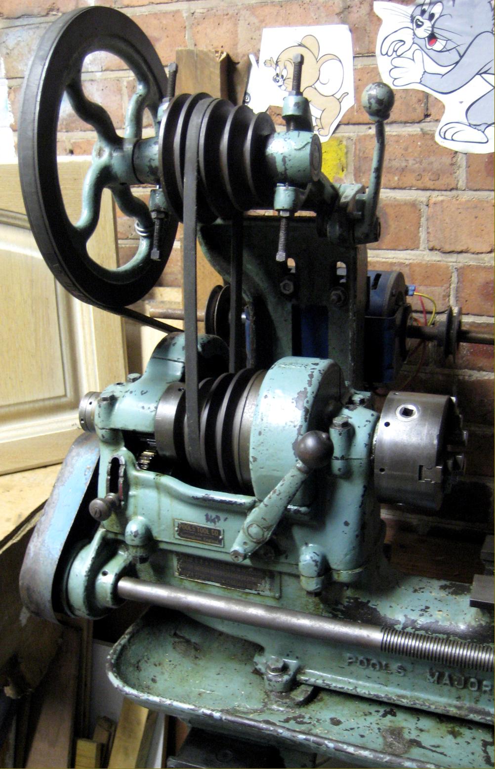
Although the spindle bearings on the Major were an improvement compared with those found on the Special, there was no positive alignment for the headstock casting on the bed, it sat on a plane surface and was held down by 4 ordinary set-screws that allowed 2 or 3 degrees of play. No doubt the makers would have set things up with a bed-mounted jig, but should a private owner disturb the setting, getting it right again takes much trial and error. One welcome improvement was the method of engaging and disengaging backgear, a single lever being used that, pivoting on the face of the headstock, operated multi-tooth dog clutches formed on the mating faces of headstock pulley and bullwheel (the latter being machined with a groove in which ran a pair of bronze shoes connected by a yolk to the lever). Drive from headstock spindle to leadscrew was by (for a small lathe) unusually wide changewheels designed to cope with the additional forces caused by the fitting of power feeds. A conventional tumble-reverse mechanism was used, but contained neatly within the headstock walls instead of outside them - as might have been expected on a lathe of this class.
Fitted with rather small, hard-to-read zeroing micrometer dials, the compound slide rest had its top slide held to the cross slide by a post turned in the form of an inverted cone (exactly like a Myford Super 7 and South Bend 9-inch). Sadly the words spoil, ship, tar and ha'peth come to mind, with only a single pusher screw through the right-hand face of the cross slide to retain it. The top slide also lacked degree graduations to measure its swivel.
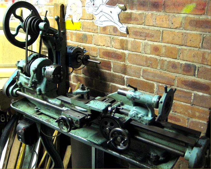
As most small lathes are better off with the top slide removed for day-to-day work, and replaced by robust toolpost mounted directly on the top slide, the owner of one machine illustrated below has made the right decision in respect of his own lathe. In order to provide a longer travel for the T-slotted cross slide (especially useful when a vertical milling slide was mounted) the saddle was cantilevered out well forward of the very light apron and also formed into a perfunctory guard for the large gear that provided a power sliding feed - though to some extent this arrangement was forced on the designers because the rearward travel of the cross-slide slide was limited by the power-feed gears mounted at the back of the saddle. A particularly well-made fixed steady, with the fingers adjusted by screws, stood out as the best in a range of ordinary accessories...
|
|
|
|
|
|
|
 |
|
|
|
 |
|
|
|
|
 |
|
|
|
|
|
|
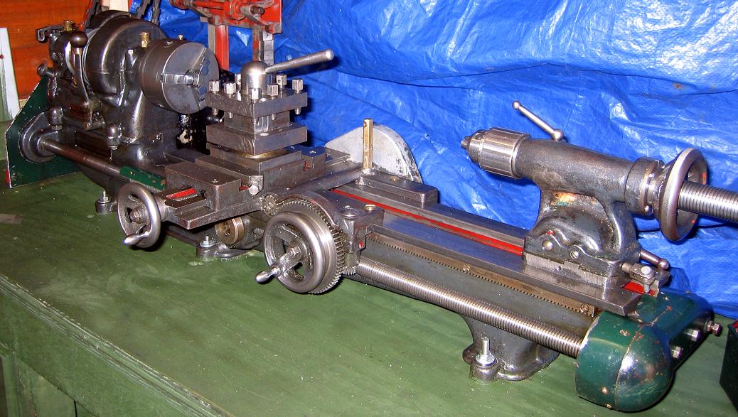
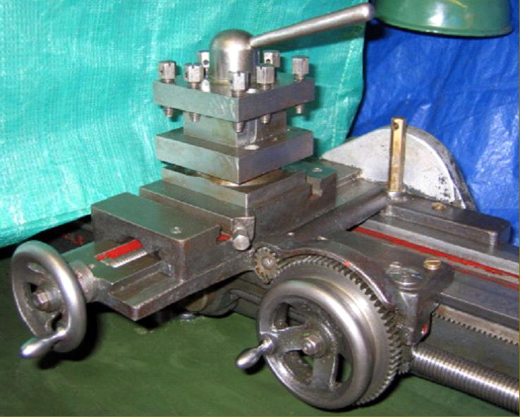
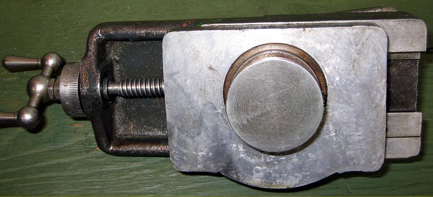
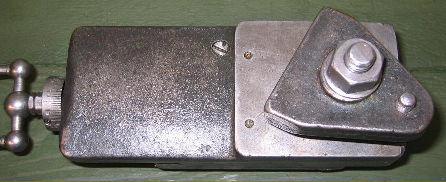
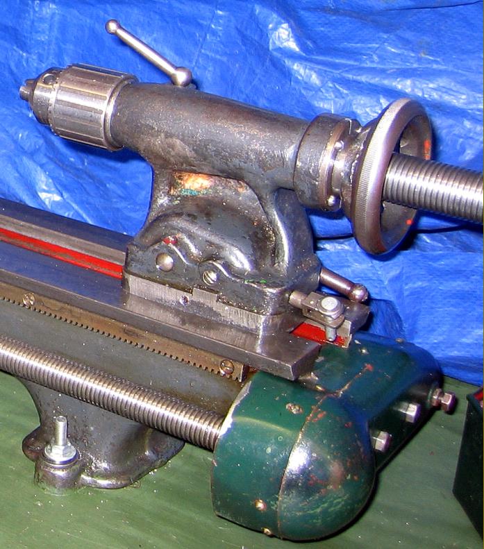
In order to provide a longer travel for the T-slotted cross slide the saddle was cantilevered out well forward of the very light apron and also formed into a perfunctory guard for the large gear that provided a power sliding feed. In order to improve tool rigidity the owner of this example has removed the top slide and replaced it (for day-to-day work) with a robust 4-way toolpost.
|
|
|
|
|
|
|
|
|
|
 |
|
|
|
|
 |
|
|
|
|
 |
|
|
|
|
|
|
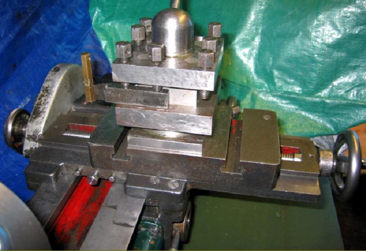
The length of the T-slotted cross slide was limited by the power-feed gears mounted at the back of the saddle. In order to improve tool rigidity on a lathe were the top slide was secured by only one pusher screw the owner of this example has wisely decided to remove the slide for day-to-day work and replace it with a robust 4-way toolpost.
|
|
|
|
|
|
|
|
|
|
 |
|
|
|
|
|
|
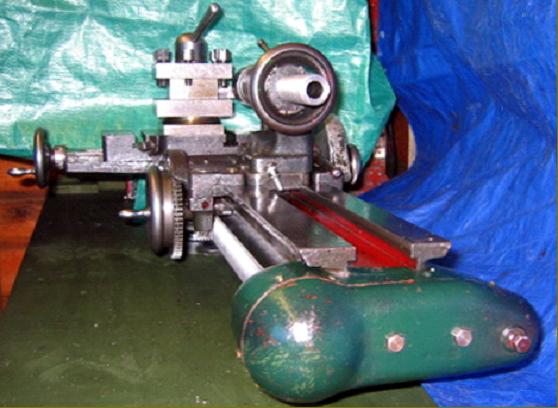
The one-piece saddle and apron, with its long extension to carry the cross-slide ways, as seen from below
|
|
|
|
|
|
|
|
|
|
 |
|
|
|
|
|
|
Headstock - cap-type spindle bearings and a single lever to engage and disengage backgear.
|
|
|
|
|
|
|
|
|
|
 |
|
|
|
|
|
|
The top slide held to the cross slide by a post turned in the form of an inverted cone (exactly like a Myford Super 7 and South Bend 9-inch) but with only a single pusher screw through the right-hand face of the cross slide to retain it.
|
|
|
|
|
|
|
|
|
|
 |
|
|
|
|
 |
|
|
|
|
 |
|
|
|
|
|
|
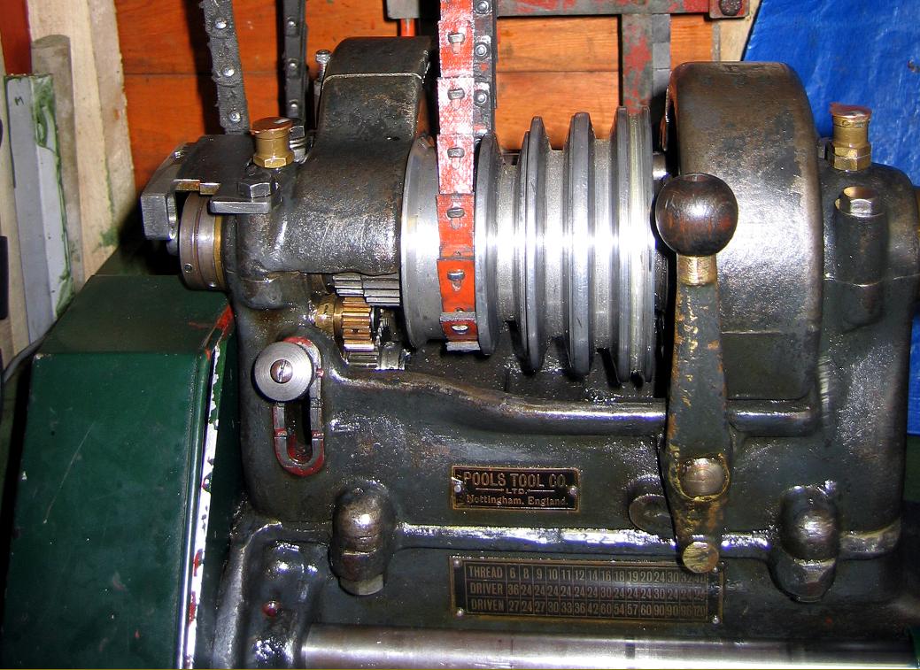
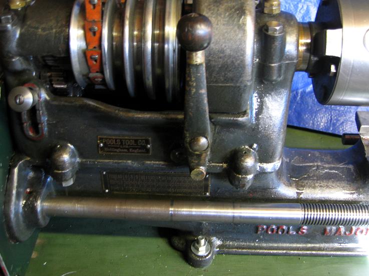
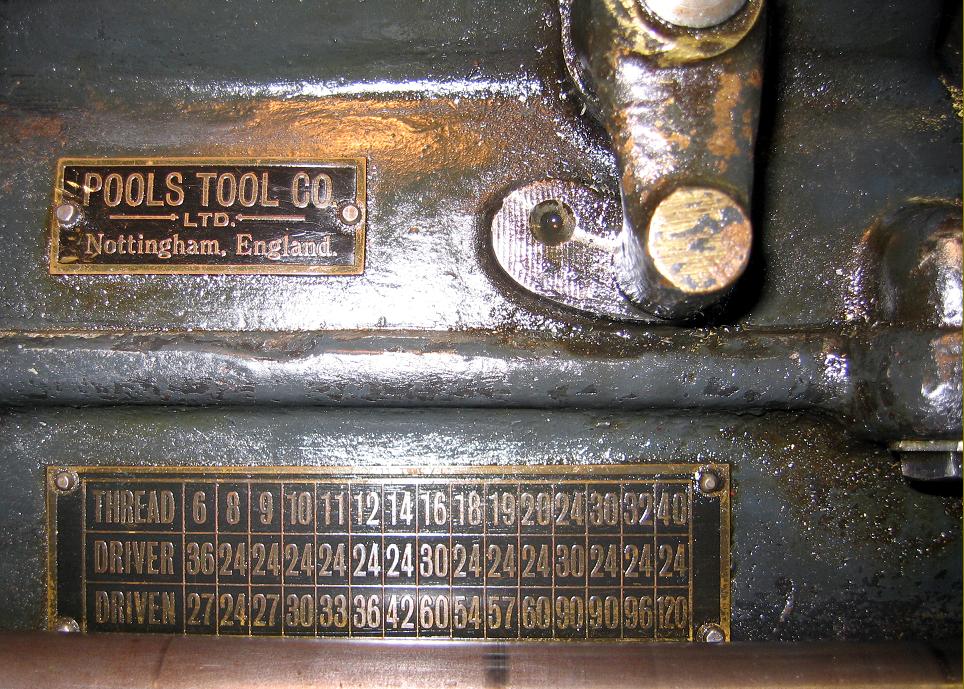
Maker's plate and screwcutting chart on the Pools major
|
|
|
|
|
|
|
|
|
|
|
|
|
|
|
 |
|
|
|
|
|
|
For a small lathe the changewheels were unusually wide and retained
on the output stud and leadscrew by neat, knurled hand-nuts.
|
|
|
|
|
|
|
 |
|
|
|
|
|
|
The arrangement of the tumble reverse mechanism and the wide but fine-pitch changewheels was very similar to that employed on the Pools "Special".
|
|
|
|
|
|
|
 |
|
|
|
|
 |
|
|
|
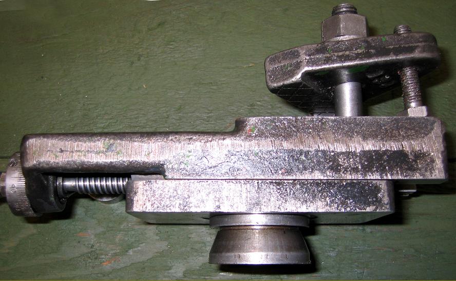
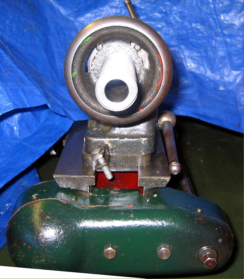
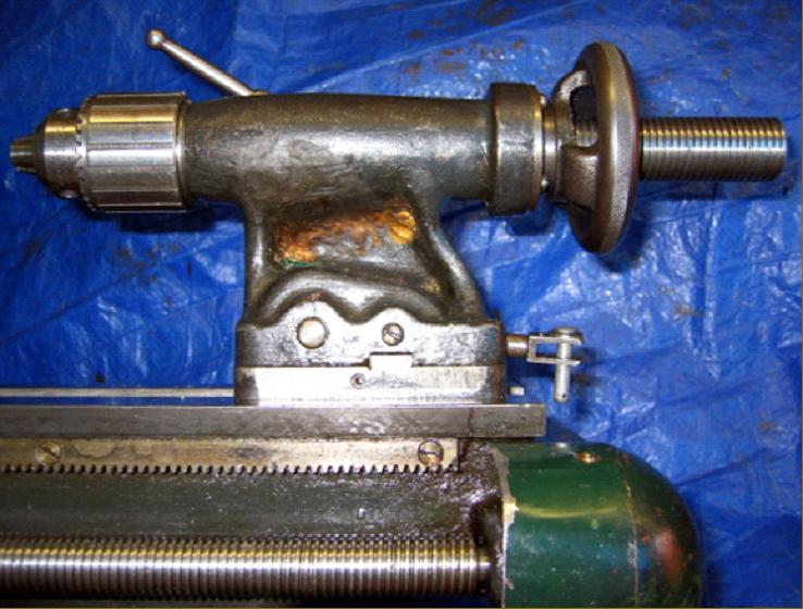
An extension to the tailstock end of the leadscrew drove a train of 4 gears set across the end of the bed. The motion was thus transferred to a shaft that lay along the back of the bed that provided, though a worm-and-wheel mechanism, power sliding and surfacing feeds.
|
|
|
|
|
|
|
|
|
 |
|
|
|
|
 |
|
|
|
|
|
|
Instead of a bolt-on plate to carry the power-feeds gear train the end of the bed was cast with an extra wide boss
|
|
|
|
|
|
|
|
|
|
 |
|
|
|
|
|
|
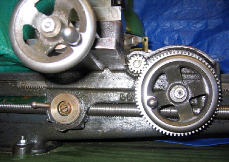
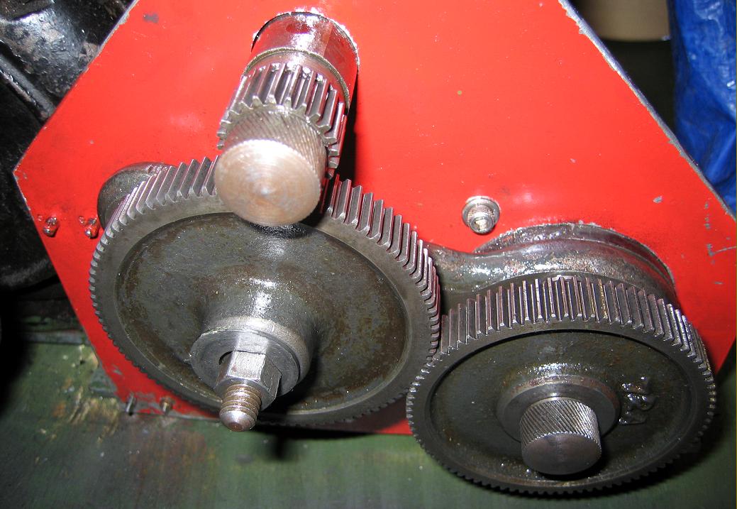
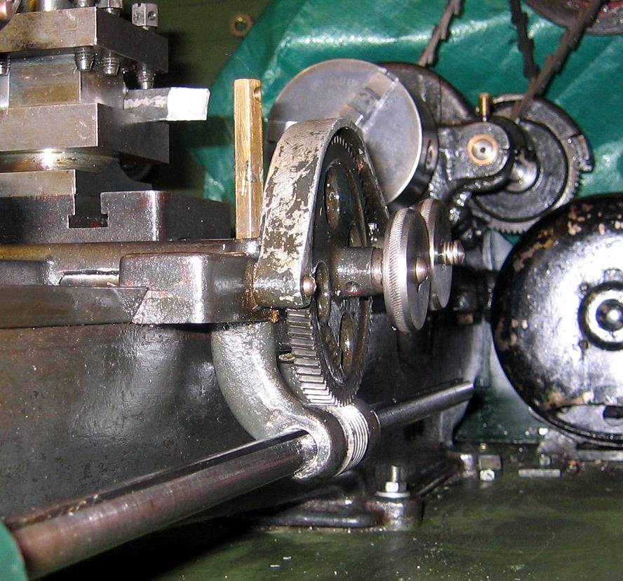
Very much an "add-on", and of a type that had fallen out of favour on larger lathes by the end of the 19th century, the power sliding and surfacing arrangement could only be described as old-fashioned--even though it worked well. A long overhung shaft mounted parallel with the rear face of the bed was given additional support by a cast bracket attached to the back of the saddle just before the shaft passed through a worm wheel. The worm wheel drove a large gear wheel, the shaft of which passed forwards through the saddle to drive a large gear on the front of the apron - this gear meshing in turn with a pinion that drove the carriage along the bed by engaging with the normal hand-feed rack. The large driven gear at the back of the bed also engaged with a smaller gear fastened directly to the end of the cross- feed screw - thus providing a surfacing feed. The mechanism was engaged by the simple means of screw-in knobs forcing the gears on to a taper at the end of their respective shaft.
|
|
|
|
|
|
|
|
|
|
 |
|
|
|
|
|
|
A view of the power sliding and surfacing drive showing the two screw-in engagement knobs
|
|
|
|
|
|
|
|
|
|
 |
|
|
|
|
|
|
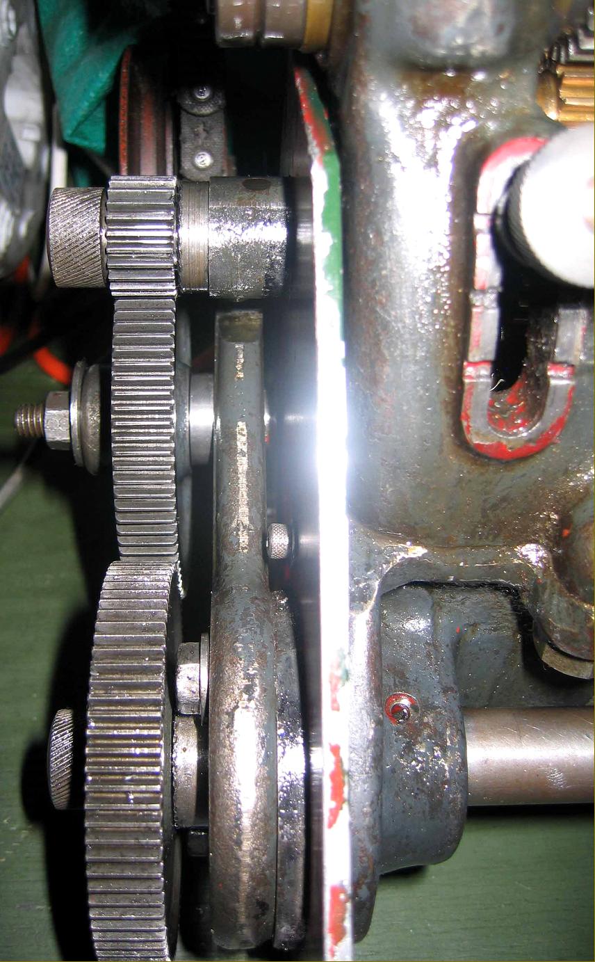
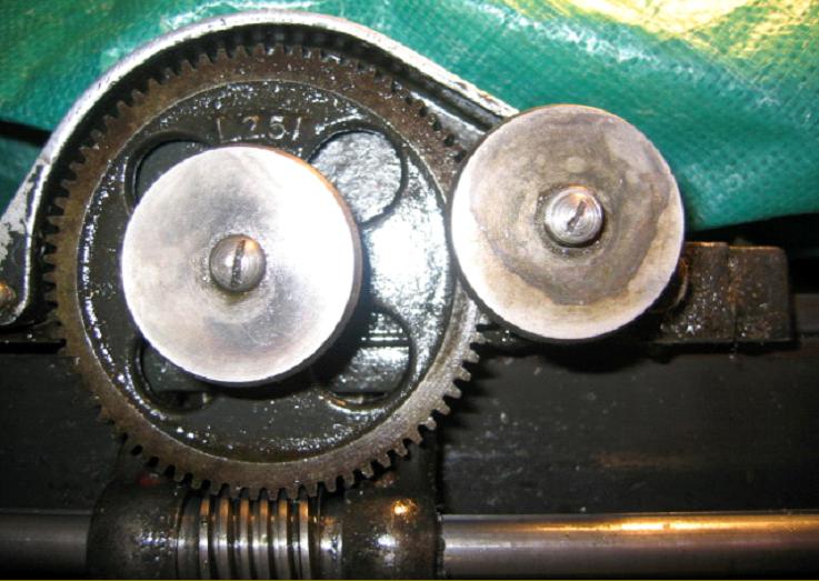
Another view of the power sliding and surfacing feeds engagement handwheels.
|
|
|
|
|
|
|
|
|
|
 |
|
|
|
|
|
|
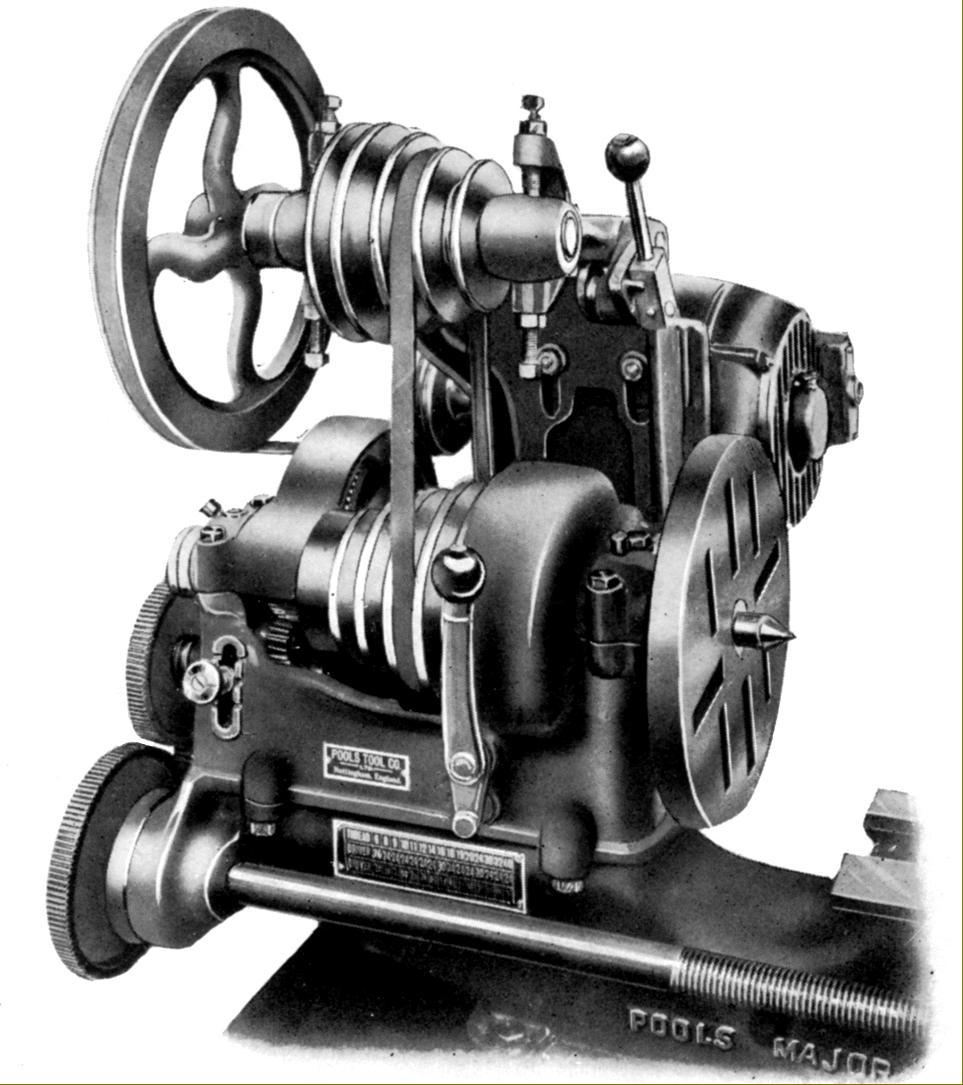
A conventional tumble reverse mechanism was used but contained neatly within the headstock walls instead of outside them as might have been expected. Note the exceptionally long headstock bearing
|
|
|
|
|
|
|
|
|
|
 |
|
|
|
|
 |
|
|
|
|
|
|
Rear view of the backgear operating mechanism
|
|
|
|
|
|
|
|
|
|
 |
|
|
|
|
|
|
Dog clutch on bullwheel and headstock pulley
|
|
|
|
|
|
|
|
|
|
|
|
|
|
|
|
 |
|
|
|
|
|
|
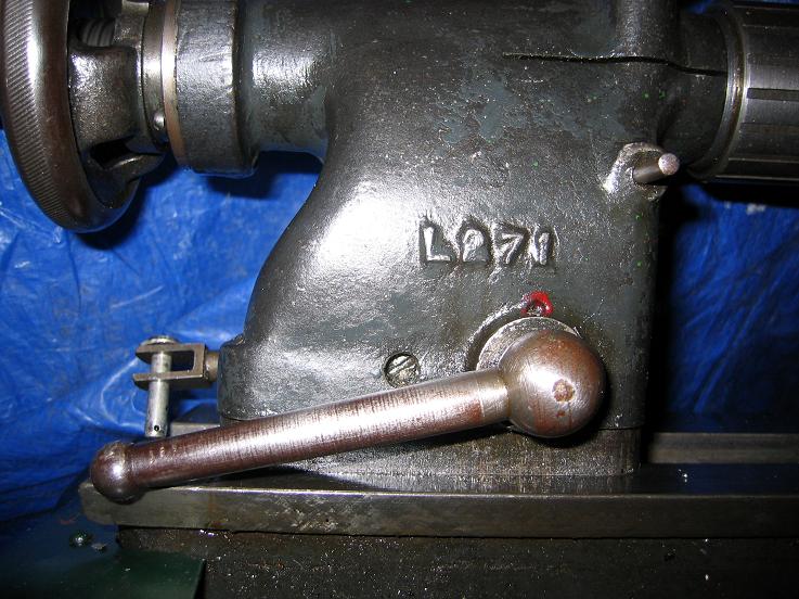
Above and below: backgear was engaged and disengaged by the movement of one lever on the face of the headstock (a single-lever backgear) - an unusual luxury on any small lathe. This was achieved by multi-tooth dog clutches formed on the mating faces of headstock pulley and bullwheel with the latter carrying a groove in which ran a pair bronze shoes connected by a yolk to the operating lever.
|
|
|
|
|
|
|
|
 |
|
|
|
|
|
 |
|
|
|
|
|
 |
|
|
|
|
|
 |
|
|
|
|
|
 |
|
|
|
|
|
|
|
|
|
|
|
|
|