
|
A. Evan Lewis |
A 4 minute video of different engines in action lifting weights
A model of Hero's steam engine was built capable of rotating at 5,400 revolutions per minute (the highest speed ever reported). To demonstate that it could perform useful work it was connected to a gearbox to reduce revolutions per minute to 122 RPM or less. This was used to lift a weight on a small crane and it lifted 200 to 300 grams to a height of 500 mm in about 15-18 seconds. From that it was calculated that it produced about 0.1 Watts of power. This is considerably less than the power output calculated from the theory of thrust produced by steam jets, which was up to 9 Watts (Appendix B). This proved that it could do work, but whether it would be considered useful work is another story.The efficiency of converting heat to mechanical work was calculated from theory to be 1% but in practice was as low as 0.0128%.
Efficiency may not matter if there is an unlimited supply of fuel, such as wood, to produce the fire necessary to generate steam. On the other hand, if it takes more labor to collect the fire wood than it saves in providing mechanical energy, perhaps it was not economic. It could however have been the beginning of the development of more efficient steam engines. Some engineers disagree (w) saying that they did not have the knowledge (thermodynamics, fluid dynamics, gear design, and boilers) to develop it further, but that is debatable. Trial and error goes a long way.
The Hero engine is now considered the first steam engine in recorded history. This web page looks at the technology and knowledge which the Greeks posessed. It can be argued that they were in a position to invent a turbine or piston driven steam engine. Hero's writings illustrate that he knew how to use expanding air or steam to do work. He was also aware of the use of pistons as pumps (described by Archimedes about 300 years earlier), and Hero even described a piston operated hypodermic syringe for medical uses. They also described a geared winch with a worm gear as the first stage. Hero's wind organ used a wind mill to move a beam with a piston at the other end, just like a beam engine. The piston pumped air into an organ to make it play. They even had some basic understanding of the behaviour of gases and proposed the existence of atoms.
The question still remains, why didn't the Greeks or other scientists and engineers put these facts together and develop more advanced steam engines (x). That did not happen until 1700 years later when development of the steam engine was key to the industrial revolution? The most common reason given is that the majority of the population in the ancient world were slaves, so engineers saw no reason to develop labor-saving devices. There is some evidence that they thought the development of labor saving devices may cause the slaves to revolt. What might they do with their muscles if they were not working?
There are several myths about Hero and his steam engine and they are addressed here. There are many references, URL links, diagrams, photos, and quotes from translations of Hero's original books in Greek. There are also appendicies containing extensive theoretical calculations.
The answer came after five years of work perfecting a Hero’s engine.
Yes, I was able to prove that it could lift a weight on a small crane.
Many people have said that it produces so little torque that simply placing your finger on the ball will stop it spinning. They considered it a useless toy. In a machine with a rotating shaft, like the Hero engine, torque is the force that it can exert at a given radius from the axle (given in pound.feet or Newton.meters).
Power can be calculated by multiplying the speed of rotation (revolutions per minute or RPM) by torque. The fact that the Hero engine can spin at a very high rate, means that it could be geared down to produce more torque. If it is geared down to produce slower rotation the torque increase as the rate of rotation decreases, but the power remains the same.
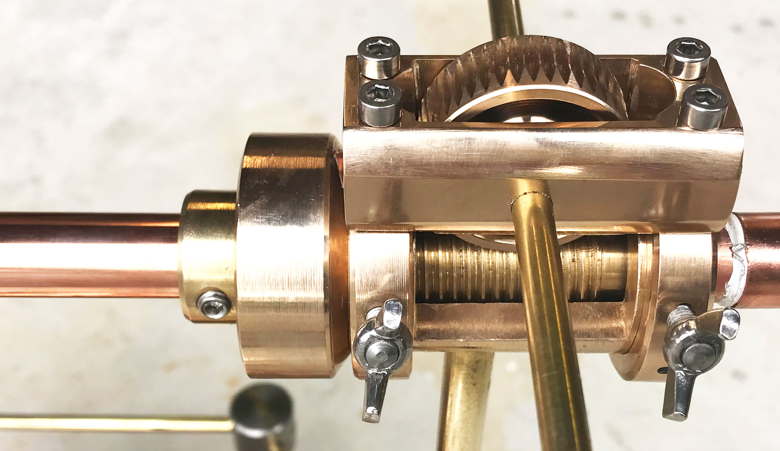
I made a worm gear that turns one time for every 44 turns of the input shaft. By reducing RPM by a factor of 44 we increase torque by a factor of 44 and this gives it enough torque to operate a crane and lift a weight (power stays the same).
The worm gear consists of a thread (20mm diameter with 1.5mm pitch) meshing with a gear wheel which has 44 teeth. For every turn of the thread it advances by one tooth, so it takes 44 turns of the shaft to make the gear wheel turn once. This type of gear reduction should produce relatively little friction.
This engine was built using a small engineers lathe and during its production a series of YouTube videos were produced, including a very simple method for making the worm drive gear (See YouTube.com/evanecent/playlists and find the playlist about lathes or use the embedded videos shown at the end of this page.)
Click to enlarge the photo
|
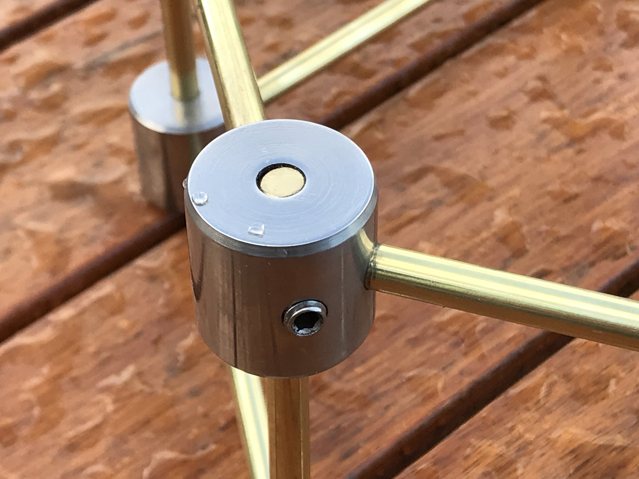
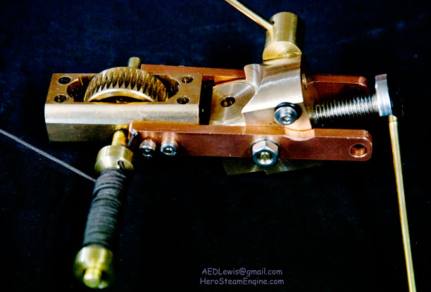
A gearbox was constructed using a worm drive similar to those described by Hero and others in the Ancient world. It is driven by a bronze thread 20mm diameter with 1.5mm pitch. This meshes with a gear wheel with 44 teeth, giving a gear reduction of 44:1. The construction method is remarkably simple and is shown in one of the short YouTube videos at the end of this page (Season 2 Episodes 1 and 2). |
The moving part was a spinning sphere with jets placed on its equator pointing along the equator. Steam rushing out of the jets created a force that made the sphere spin. It wasn’t until 1690 AD that Sir Isaac Newton proposed the three laws of motion that we still use today. The third law states that “Every action produces a reaction equal in force and opposite in direction”. In this case the force that causes the steam to rush out of the jets causes an equal and opposite force on the jet itself and that makes the sphere turn. This is the same way that rockets, jet engines and other aircraft engines work.
Hero was the first to write about windmills and he may have thought that the escaping steam was pushing on its surroundings like wind pushing the sails on a windmill, causing the motion of the sphere relative to its surroundings. Hero also described a device with dancing figures on a stage that rotated using the same principal as his steam engine, except that it was driven by air which expanded when heated by a fire (below). Hero used this explanation: “the air, growing hot, will pass through … the smaller tubes [jets]; when, meeting with resistance from the sides of the altar, it will cause the tube and the dancing figures to revolve.”
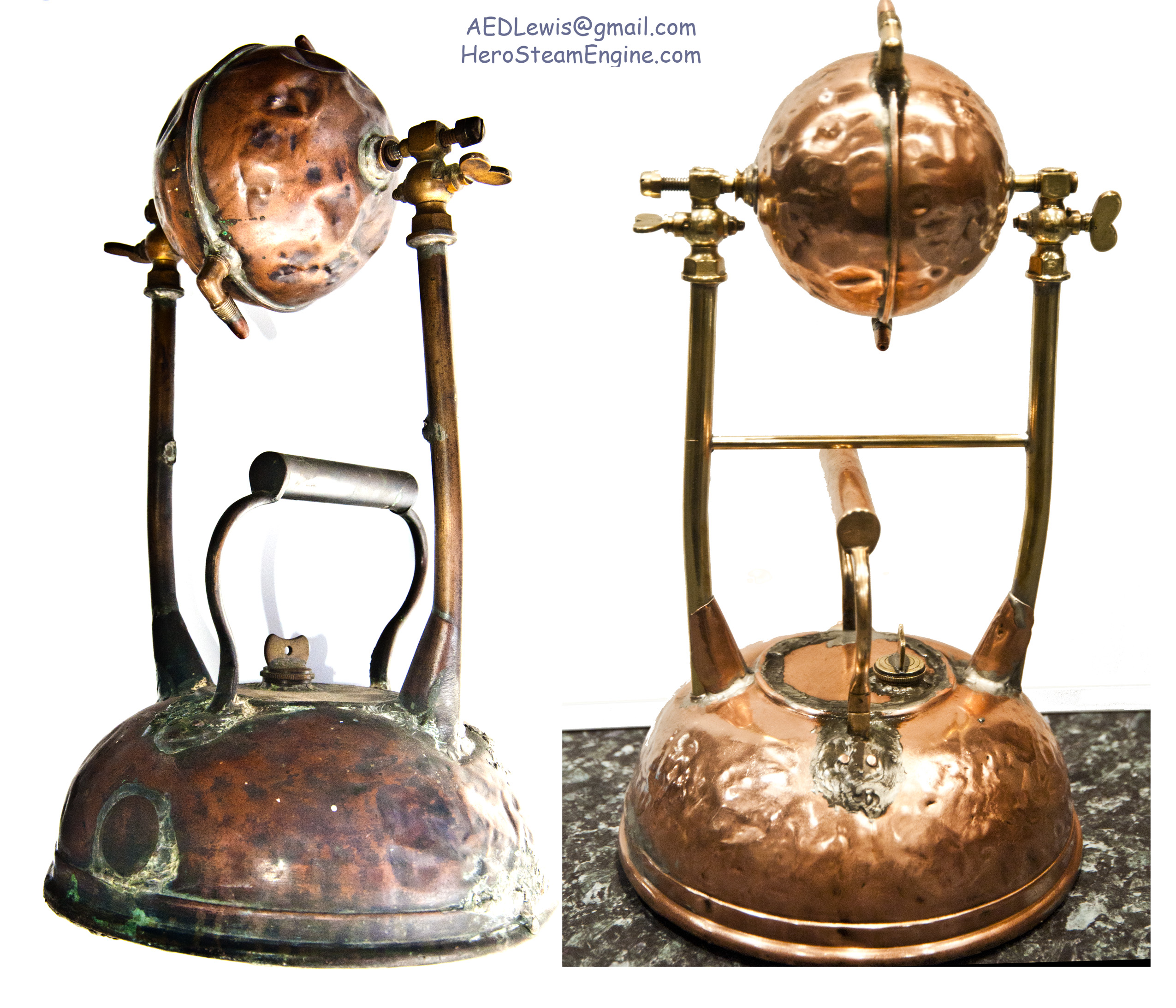
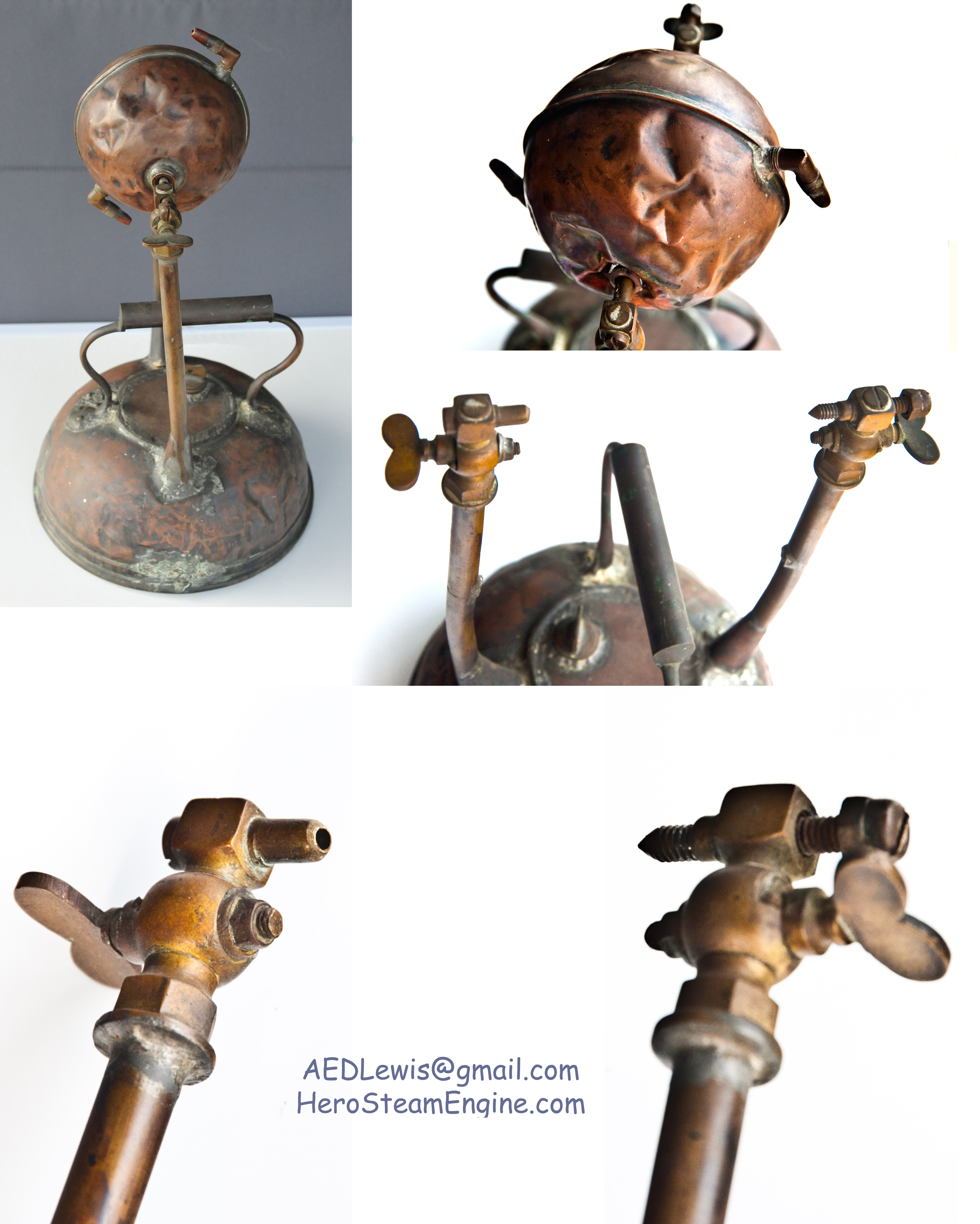
I became interested in Hero’s steam engine when I inherited a model of the ‘aeolipile’ from my Grandfather, Hugh Sargeant Barrett, who was a stationary steam engine engineer. He made this model by using a large copper kettle as a boiler (3.5 liters) to produce steam which was conducted up vertical pipes. These pipes supported a copper sphere (which had been the float in a toilet cistern) supported between two pointed pivots. I saw this operating as a child but now it was badly dented and the base had blown out of the kettle when it had been allowed to run dry.
|
The Hero's engine when I inherited it from my mother and her father had been quite badly damaged. It was restored to working order. |
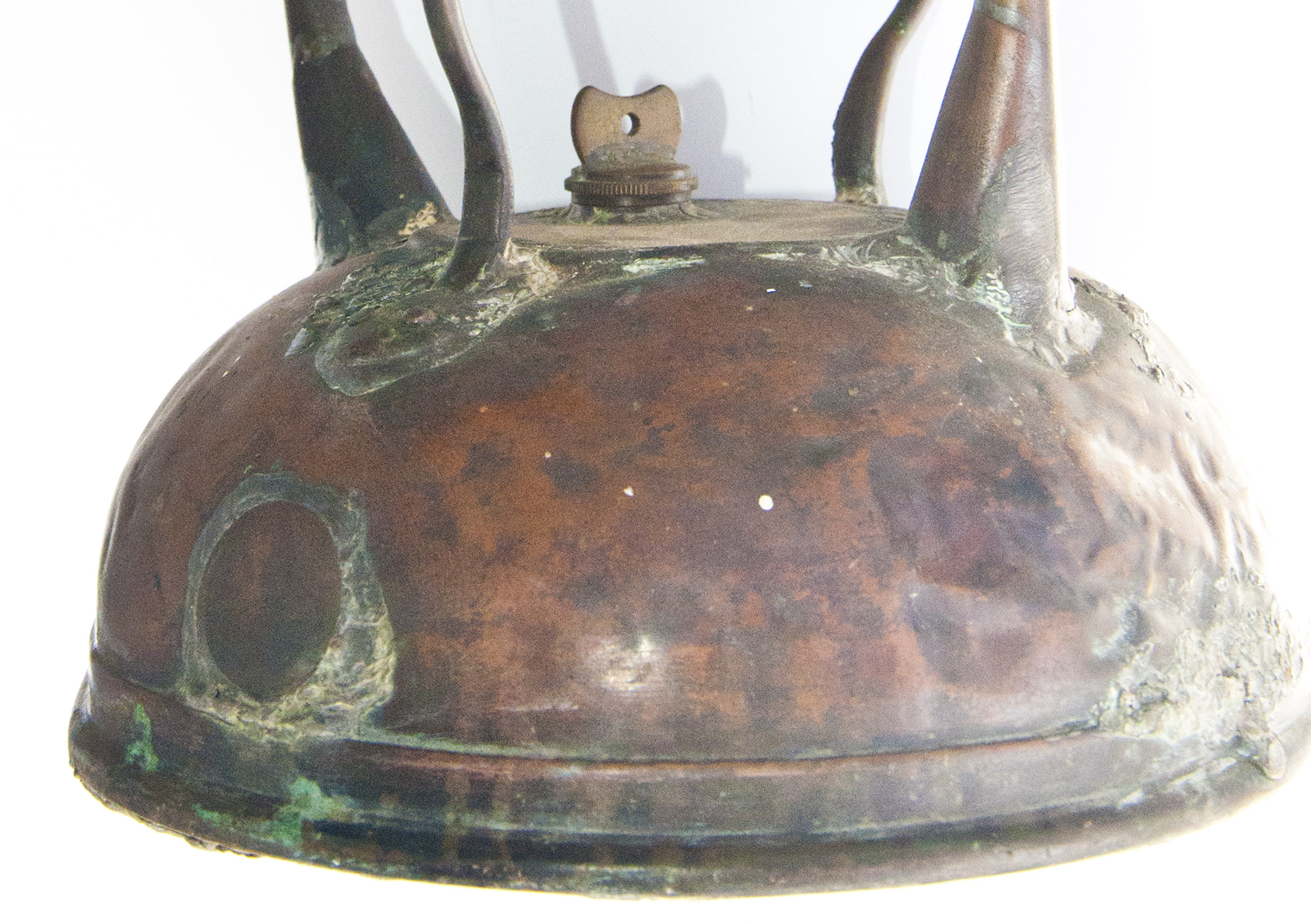
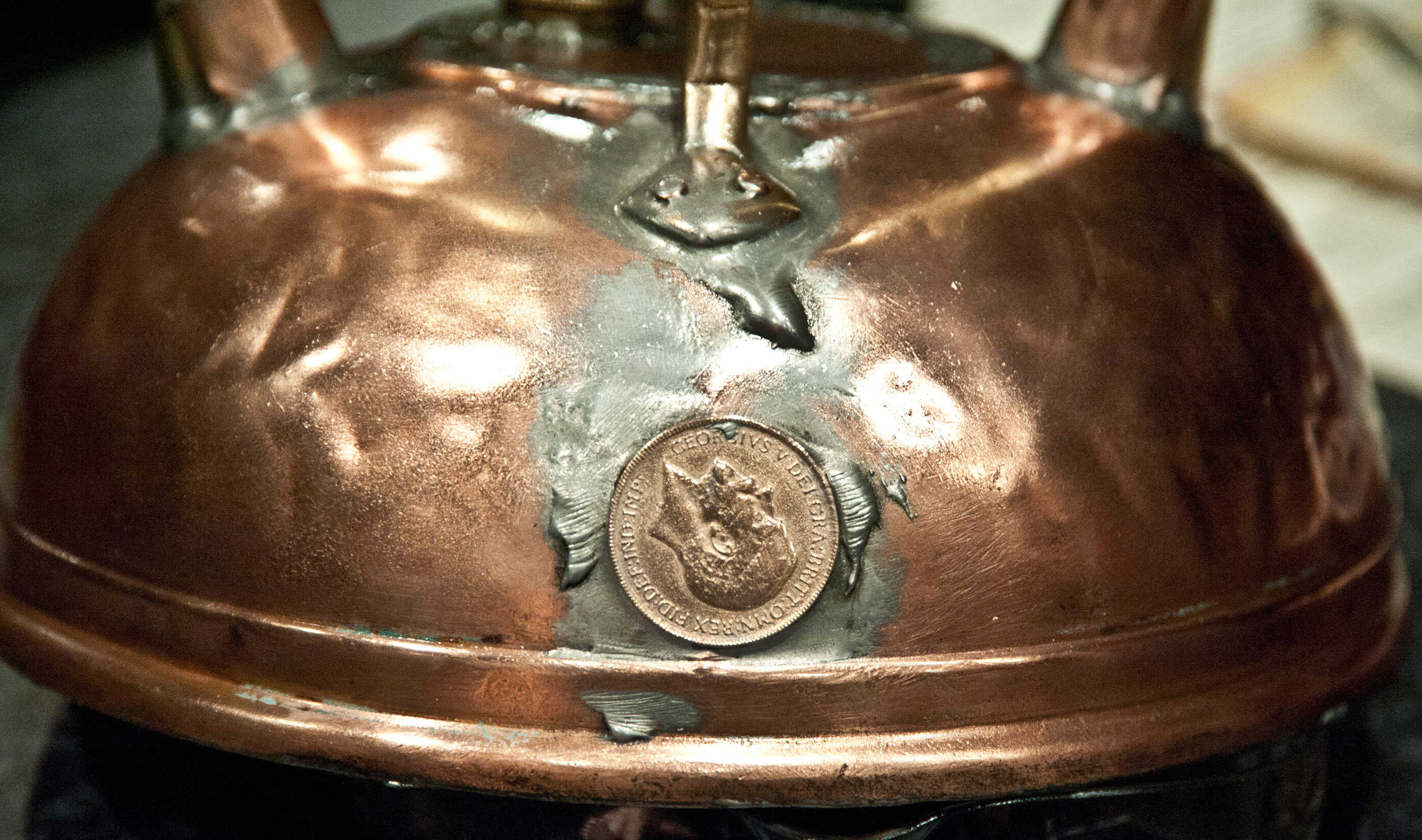
Rather than try to repair my grandfather's engine I decided to build my own version. But eventually, with the help of a local radiator repair man, Graeme Galyer, we took it apart. There was a polished round copper plate covering the hole where the spout of the kettle had been.
When it fell off we found it was an old English penny with the image of George the Fifth on it. He reigned from 1910 when Hugh was 32 years old. To continue the tradition, the newer versions now have coins in them as well. We soldered the joints back together again and it worked. We couldn't get inside the sphere to knock the dents out and restore some resemblance to a sphere so we had to push the dents out with a rod inserted through holes in the sphere.
Click to enlarge the photo
|
Hugh Barrett's Hero engine had a polished copper plate covering the hole where the spout of the kettle had been. |
Click to enlarge the photo
|
When the copper plate fell off, we found that it was a penny with an image of George the fifth of UK. |
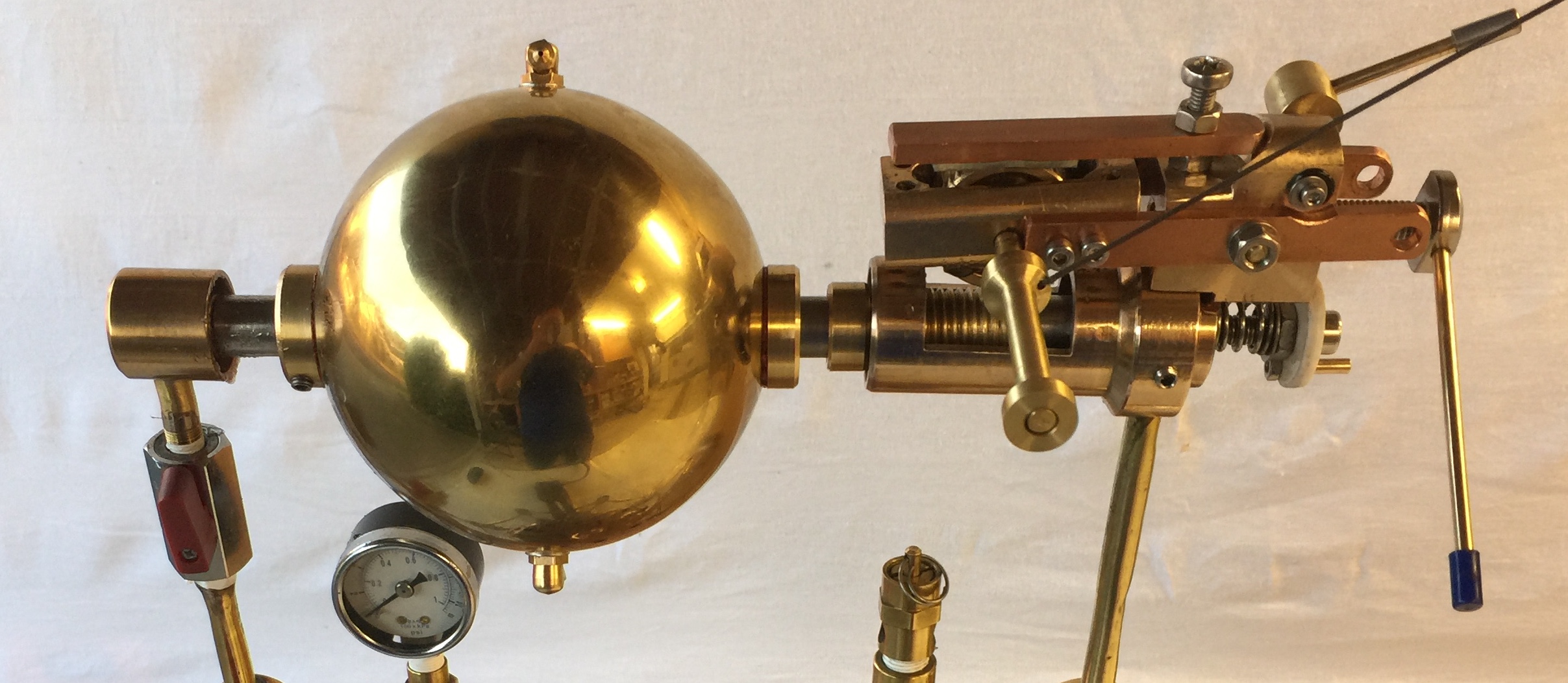
My grandfather's engine ran at 2400 RPM. But the ball was badly balanced and when I allowed it to run faster (using compressed air instead of steam at a public display) it shook itself to bits and the ball went bouncing at speed across a field. It was easily repaired but clearly we needed to make one that was well balanced and perhaps it would run even faster.
Modern turbines can exceed 30,000 RPM. The absolute maximum speed (if the jets of Hero's engine were able to reach the speed of sound) was calculated to be 60,000 RPM (Appendix B in subsection Maximum possible RPM). But as the jets approach the speed of sound their thrust diminishes towards zero. This means that the jets might be able to approach the speed of sound (mach 1), but can never reach it. In reality Hero's engine only reached 5,400 RPM with jet velocity of about one eleventh of the speed of sound in steam, and actual air speed of 122 km/h or 73 MPH.
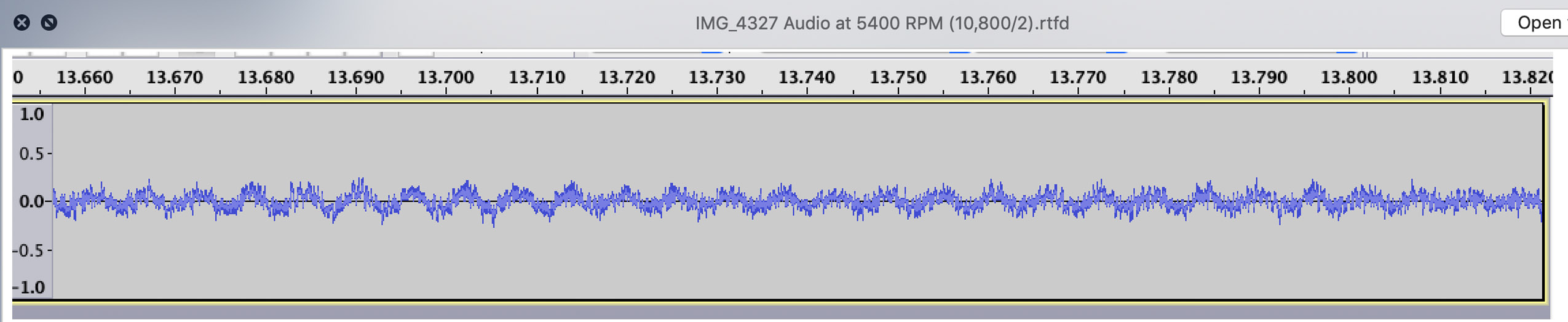
Revolutions per minute were calculated from a video recording by measuring how far a jet moved in one frame which is 1/30th second. The result was 2400 RPM. Video was recorded with an Apple iPhone 6 plus and the frame rate can be changed in 'Settings > Camera > Video' to 30 or 60 frames per second and slow motion recording is 240 frames per second. This can be useful for assessing speed of rotation by counting how many frames it takes to complete a single rotation (typically 3 to 6). Reflector tape on the sphere helps. Analysis of the sound track (a sample is shown below) using Audacity.app showed a clear cyclic pattern at 4800 from the two jets confirming the speed as 2400 RPM. A laser counter also confirmed the speed but often produced quite erratic readings even using a black disc with a strip of white reflector tape.Later, when a small crane was connected to my Hero's engine, the speed could be calculated from the rate the weight was rising on the crane, but this gave RPM under load, which is slower than the unloaded speed.
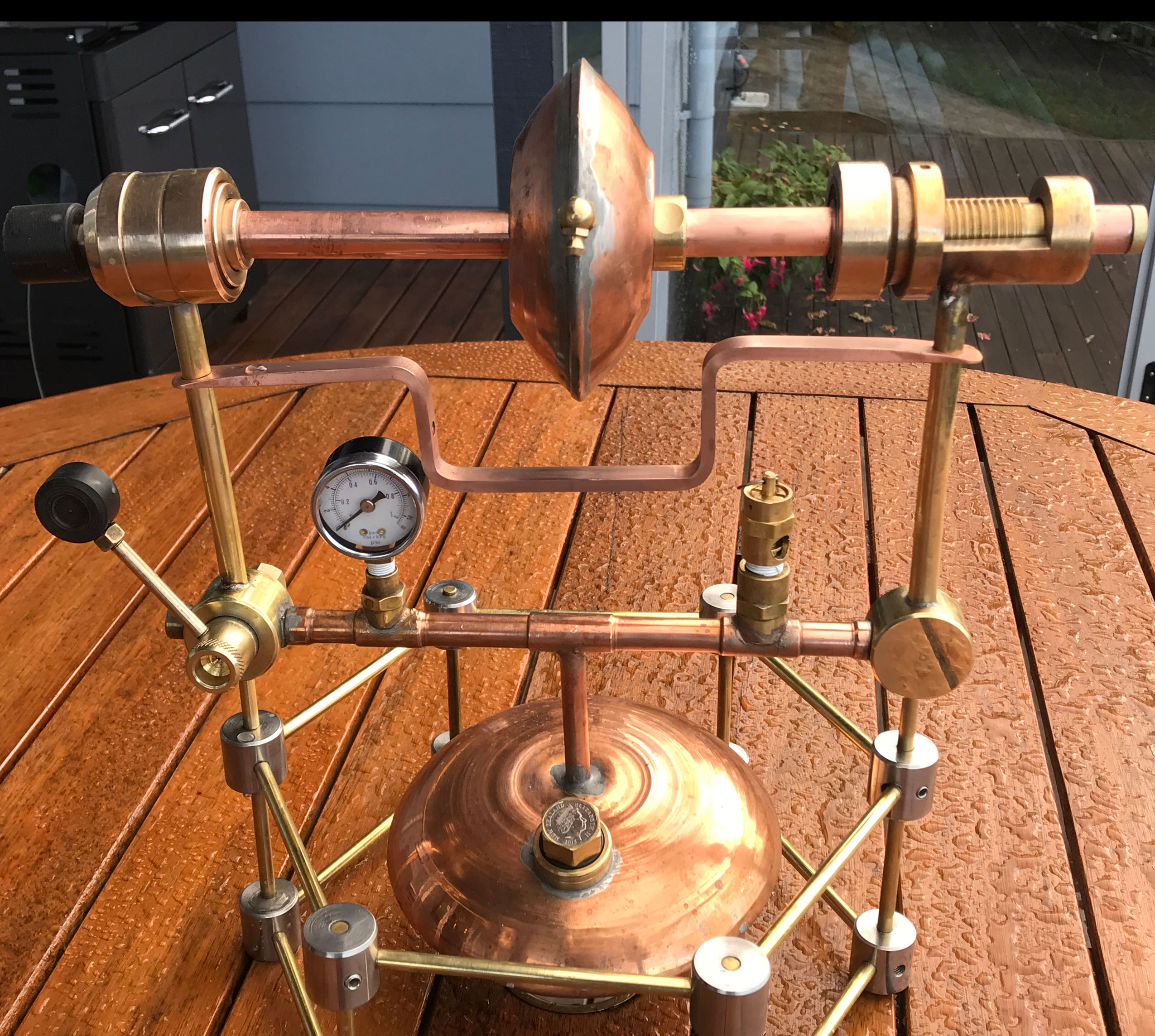
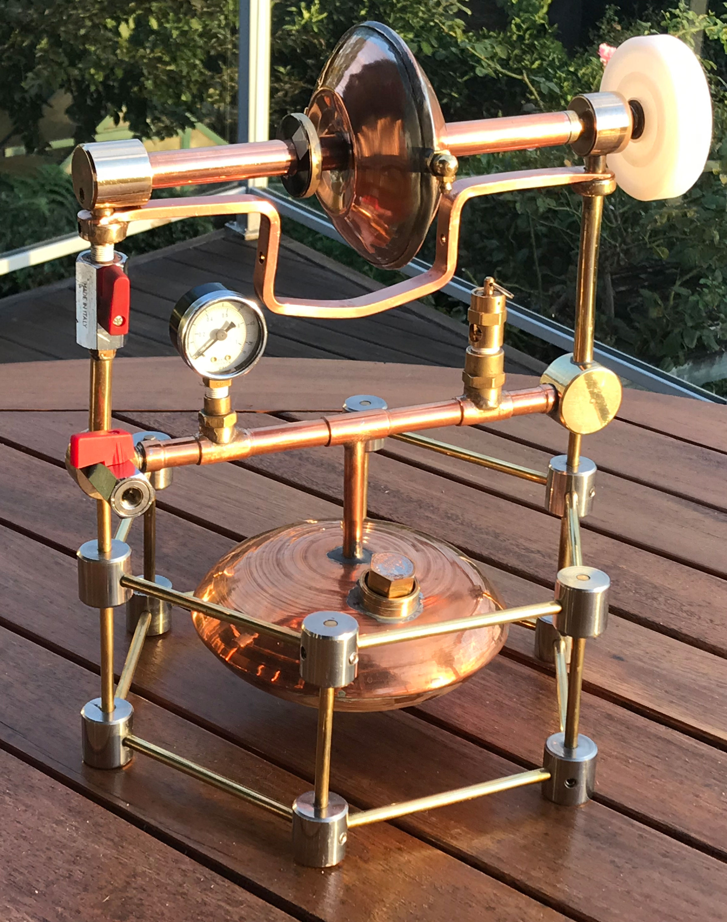
Version 1 was my Grandfather’s engine. For safety reasons my Hero engines, referred to as versions 2 and 3 used a small elliptical boiler. Version 2 was built with ball bearing races, but because they had to be sealed to prevent steam from escaping they created too much friction and it would not run. So I scrapped that idea and rebuilt it with plain phosphor-bronze bearings. But they too seemed to create too much friction.
Click to enlarge the photo
|
My first Hero's engines with ball bearings or plain bronze bearings did not work. The first working version had simple pivots and this was referred to as version 2. It was built in the old style with copper and copper alloys: mostly bronze and a little brass. |
Click to enlarge the photo
|
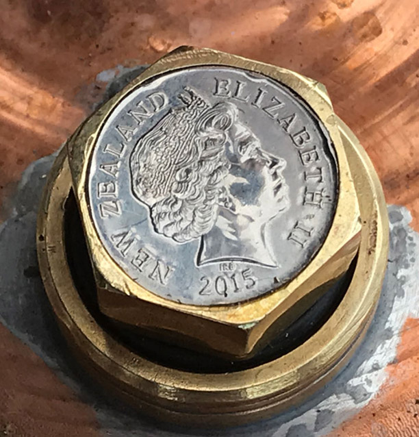
Since my grandfather had unintentionally given us a clue to the date of manufacture (after 1910), I deliberately incorporated a dated New Zealand coin in my Hero's engine filler cap. This shows Queen Elizabeth II. |
So I looked back at my grandfather's engine and the Greek drawings and found that they used small pivots with much less surface area and thus reduced friction. So all susequent versions were built with pivots and they worked. This convinced me that the Greeks actually built these machines and knew exactly what they were doing, and so did my grandfather.
Click to enlarge the photo
|
Hero's engine version 3 with simple pivots at each end of the shaft and a one liter elliptoidal boiler. |
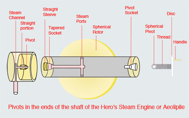
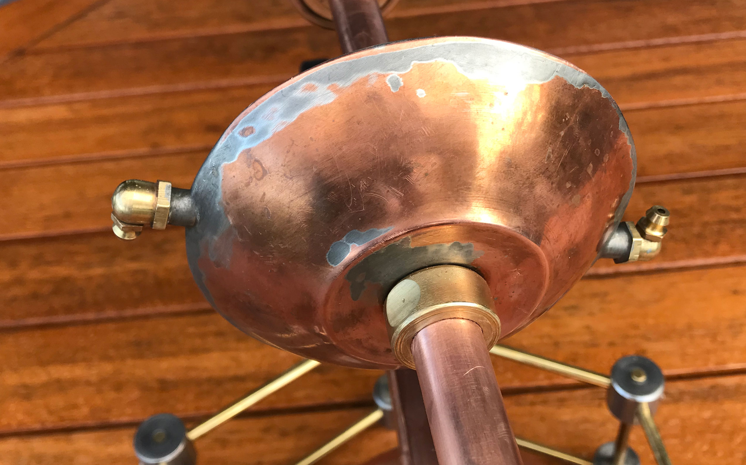
The two pivots I used initially were conical pins that were stationary, inserted into cone shaped recesses on the ends of the rotating shaft. One of these pivots has steam entering through a hole in the center of the stationary pin and moving into the cone shaped recess with a hole in the center. As an added safety feature these joints were surrounded by a metal ring or sleeve so that if the joint came apart the shaft would be retained in the ring. This actually occurred several times.
From the pivot the steam moved into the rotating shaft, into the ball and out through the jets. The pivot on the opposite end of the shaft does not have to provide steam but is mounted on a screw that can be tightened. This increases pressure on both pivots and reduces the steam that tends to escape around the pivot. This allows the steam pressure to increase which tends to produce increasing speed. But as the screw is tightened the friction increases and the rotation slows down. It is difficult to get the perfect balance between these opposing factors. Also if the rotating shaft was not in perfect alignment with the axis of the pivot it would leak steam.
I looked back at my grandfather’s engine and realized that his pivot was not a perfect cone but slightly rounded like part of a small sphere about 6mm in diameter. I had thought this had been roughly machined, but then realized that the shape may have been by design and I changed mine to match. A sphere fitted into a cone shaped recess will seal with minimal surface area touching and this minimizes friction. It also meant that alignment was not critical. On the other a hand, a cone seated in a cone can create an enormous amount of friction especially if the angle of the cone is shallow. On lathes and other tools we make use of this fact with Morse tapers which have a cone angle of about 1.5 degrees and can lock in so tightly that they can hold a drill chuck while drilling holes in steel.
Click to enlarge the photo
|
The pivots found in my grandfather's engine. The left pivot has a hole in the center for the steam to enter the rotor and it is slightly rounded. The right pivot is on a thread so that the distance between the two pivots can be adjusted and this alters the pressure applied to the left pivot. In the top left image there is a tiny pulley mounted over the pivot on the sphere. My grandfather must have tried to drive something with it. Driving a large pulley would have provided a good reduction in RPM. Unfortunately I don't have any records of what he did with it. |
Origanally I used a cone with a surface at 30 degrees to the axis (using a center drill). This design worked quite well and it ran at speeds up to 3,300 RPM. A speed of 5,400 RPM was recorded with no load on version 4 which was balanced more precisely. Despite improved balance it still rattled and by watching the steam escape from the pivot I could see it was pulsating in time with the rattle. This was caused by the shaft oscillating backwards and forwards along it's axis. If the adjustable pivot was tightened the rattle stopped but the sphere slowed down due to increased friction. It was very difficult to get the tension between the pivots perfect. They needed to be a bit loose to allow it to pick up speed, but at high speed it was possible to tighten the pivots so that less steam escaped and the pressure increased causing the speed to increase further. With bigger jets it was necessary to minimize steam loss but if the pressure applied to the pivots was increaased the friction actually made it stop spinning.
It took another careful examination of my grandfather's Hero engine to realize that the angle he used was shallower at about 45 degrees. I thought the shallower the better, so I tried the tip of a drill which has an angle of 88 degrees from the axis. The pivots jumped out with this angle. Finally I followed my grandfather's design exactly: ball shaped sationary pivot on both ends, seated in a cone shaped recess in the rotating shaft cut at an angle of 45 degrees. This gave the best results. The steam escaping through the pivot actually provides a cushion of pressurized steam for it to float on. Consequently steam loss cannot be completely stopped. But to reduce steam loss I placed the pivots inside sleeves so that the steam had to escape through a small gap between the pivot and the sleeve (see the diagram).
All the modern designs I have seen appear to allow the steam to enter through one pivot while using the other to adjust the amount of pressure applied between the pivots, as described above. If steam was allowed to enter through both pivots it would allow both to ride on a cushion of steam and may help to minimize friction. Will this be version 5?
Click to enlarge the photo
|
Pivots used in Hero Engine version 4. The shaft through the rotating ball is shown at top left. It is made of stainless steel with bronze inserts in the ends. Each of the inserts has a cone shaped recess for the pivots to fit into.
In the bottom left image there is a stainless steel screw with a spherical tip. This does not have a hole for steam entry, but the screw can be wound in by the operator to increase the pressure applied to both pivots. The image at botton right is the pivot with a hole in the center for steam to pass from here into the rotating shaft shown above. This pivot was originally cone shaped but has been rounded off to reduce the amount of surface area that is in contact with the cone shaped recess. The base of this pivot has parallel sides that fit neatly into a parallel sided recess in the shaft. Any steam leaking from the pivot has to get through this small gap to escape. The sleeve around the outside of this pivot is a safety feature. If the pivots adjustment is too loose the shaft can jump off the pivot but is retained by this sleeve. |
Click to enlarge the photo
|
This schematic sketch is not an engineering drawing but treats the shaft as though it is glass so that you can see the recesses cut for the pivots. |
Simply searching Google and YouTube will reveal many versions of Hero’s engine. Many are simplified designs which do not require a separate boiler. Instead water is placed in the sphere (or cylinder) and heat applied directly to the sphere causing the water to boil and escape from the jets. To prevent water from escaping from the jets the sphere is allowed to spin on a vertical axis instead of a horizontal one.
One very skilled model builder , John Bentley (v), built a Hero’s engine that looks just like the original diagram. He used a plain sleeve bearing instead of a pivot on the side that steam was entering, but used a screw pivot on the opposite side. The pressure of the steam pushed the shaft onto the pivot. He is the only other model builder who has reported the speed at which the engine operated. His engine achieved 1500 RPM with a steam pressure of 1.8 pounds per square inch (psi) steam pressure and jets that were 1/32 inch or 0.89 mm in diameter.

Click to enlarge the photo
|
This beautiful reproduction of Hero's engine following the appearance of these machines in the ancient or medieval literature was built by expert model maker John Bentley. He may be the only other person who has reported the steam pressure, jet size and RPM achieved by a Hero's engine. |
Versions 2 and 3 of my Hero Engine had a one liter boiler in the shape of a rotated ellipse which looked nice. So that I would not have to interfere with its integrity I suspended it inside a hexagonal brass cage with stainless steel nodes.
Click to enlarge the photo
|
A close-up photo of the elliptical boiler used in versions 2 and 3 of the Hero's engine. |
Click to enlarge the photo
|
One of the 12 stainless steel nodes used to create a hexaagonal cage where the boiler could be suspended. Grub screws have been placed in the underside to secure the horizontal rods. |
Click to enlarge the photo
|
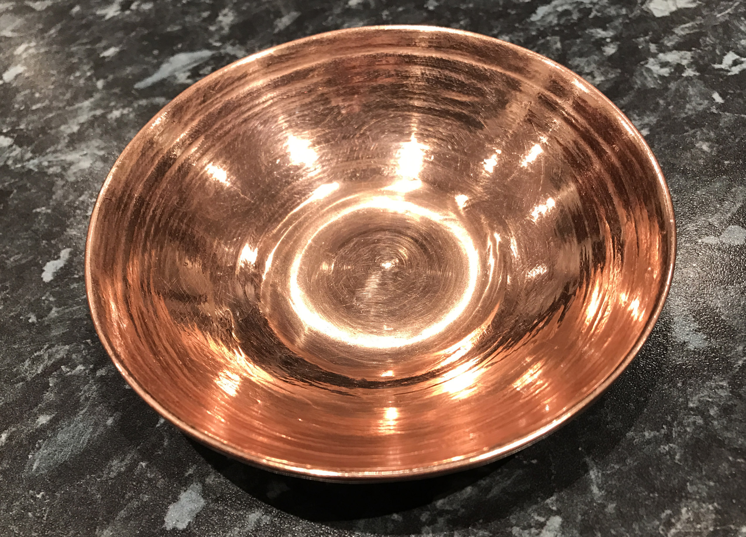
The process of spinning copper from a flat sheet into the shape of a bowl resulted in some nice copper bowls as gifts, but even after softening the copper by annealing I could not form a pair of hemispheres that could be joined together to make a sphere. The copper buckled. I was using a wooden pattern and it probably would have been more successful with a steel pattern but that would have required a large chunk of steel. |
Although this worked, the engine quickly ran out of steam pressure. It ran really well on compressed air. The elliptical boiler was one liter and my grandfather’s kettle boiler held 3.5 liters and was able to produce much more steam, capable of supplying large jets of 2mm.
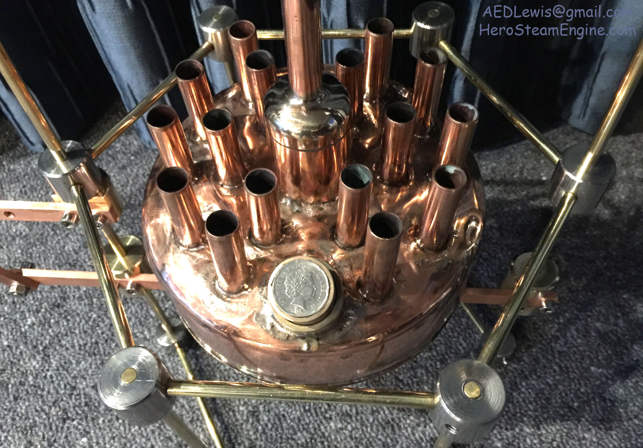
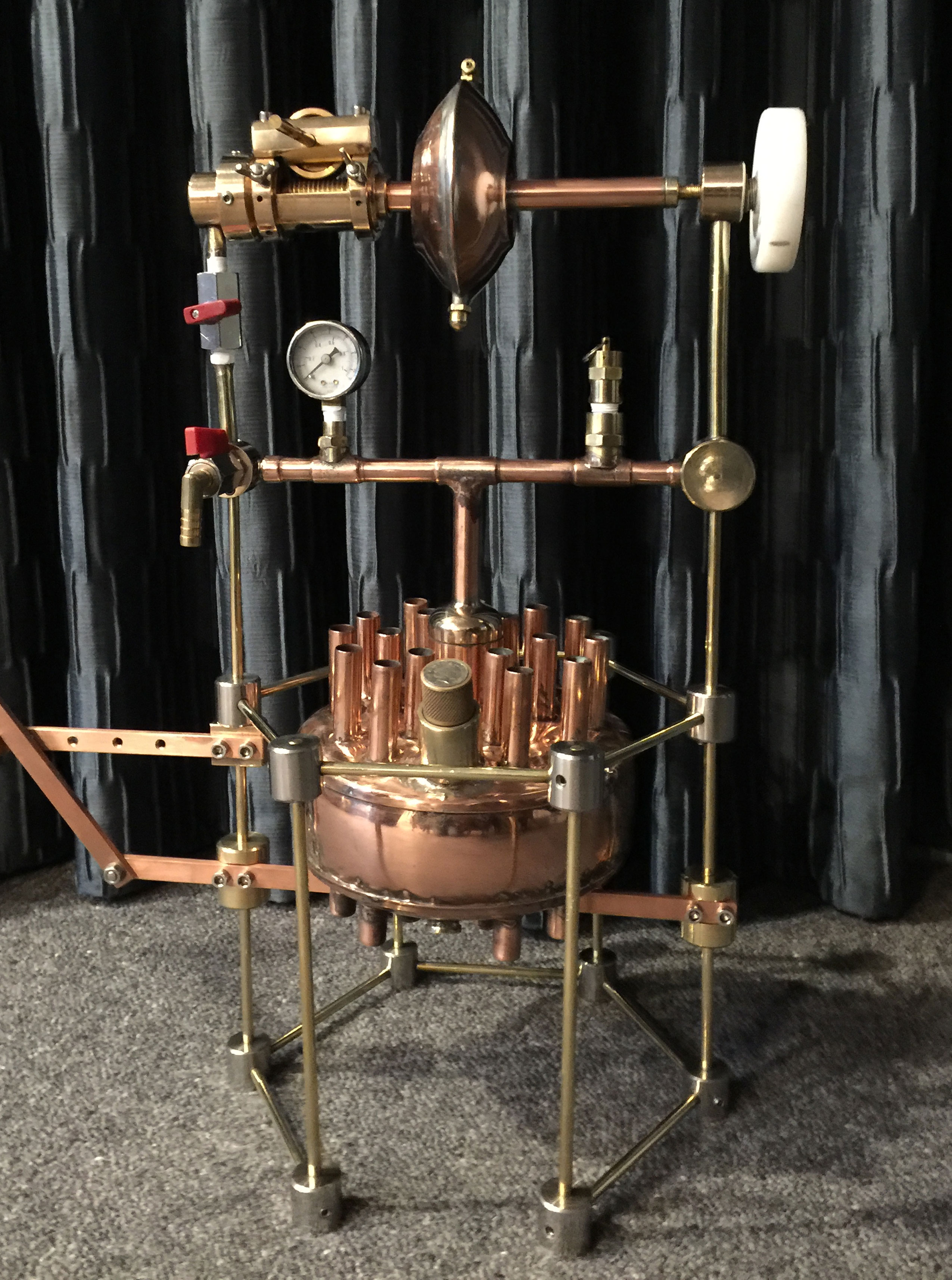
I increased the surface area for conducting heat by passing 17 copper tubes vertically through the boiler. They were attached with Silfos brand rods containing 5% to 15% silver. Hot gases from the propane burner pass through these tubes heating the water rapidly. This produced steam faster than the old boiler without tubes. It also made the boiler very strong.
For safety reasons, rather than making a large boiler I decided to make a new small boiler with increased surface area to conduct heat more rapidly into the water and thus produce steam more rapidly. In Hero’s time the same could have been achieved just by making a slightly bigger boiler with an equally large surface area and using a large fire, but it may not have been as safe, especially with a flat top. This point must be emphasised because the use of the more modern idea of boiler tubes and a propane burner could be critized. The actual method used to produce the steam is felt to be of seconday importance to demonstrating the function and performance of the rotor. I'm sure the Greeks could produce as much steam as they needed, but probably could not handle high steam pressures which exceed 100 psi in modern boilers.
Increasing the diameter of a cylindrical boiler with a flat bottom from 200mm (8 inches) to 350mm (14 inches) is all that would be required (Appendix F) to give the same surface area as my 200mm boiler with tubes, but my lathe cannot handle that size. If the boiler was in the shape of half a sphere like the cauldron in the drawings, the diameter could be reduced even more. The area of a flat disc is Pi.r squared while the area of of half a sphere is 2.Pi.r squared. The radius or diameter can be cut in half by using the cauldron design instead of a flat bottom! Rather than 350mm, a diameter of 175mm (6.9 inches) would give the same surface area for heating the water. Surprisingly this is a smaller diameter than the almost flat bottomed boiler I used. If I build version 5, I might consider this option but I had problems trying to spin anealed copper into a hemisphere on a wooden pattern (see my Youtube videos on spinning copper below).
Click to enlarge the photo
|
The new boiler with 17 vertical copper tubes to increase the surface area without using a large tank. The dome in the center is a water trap to try to prevent water from entering the system along with the steam. |
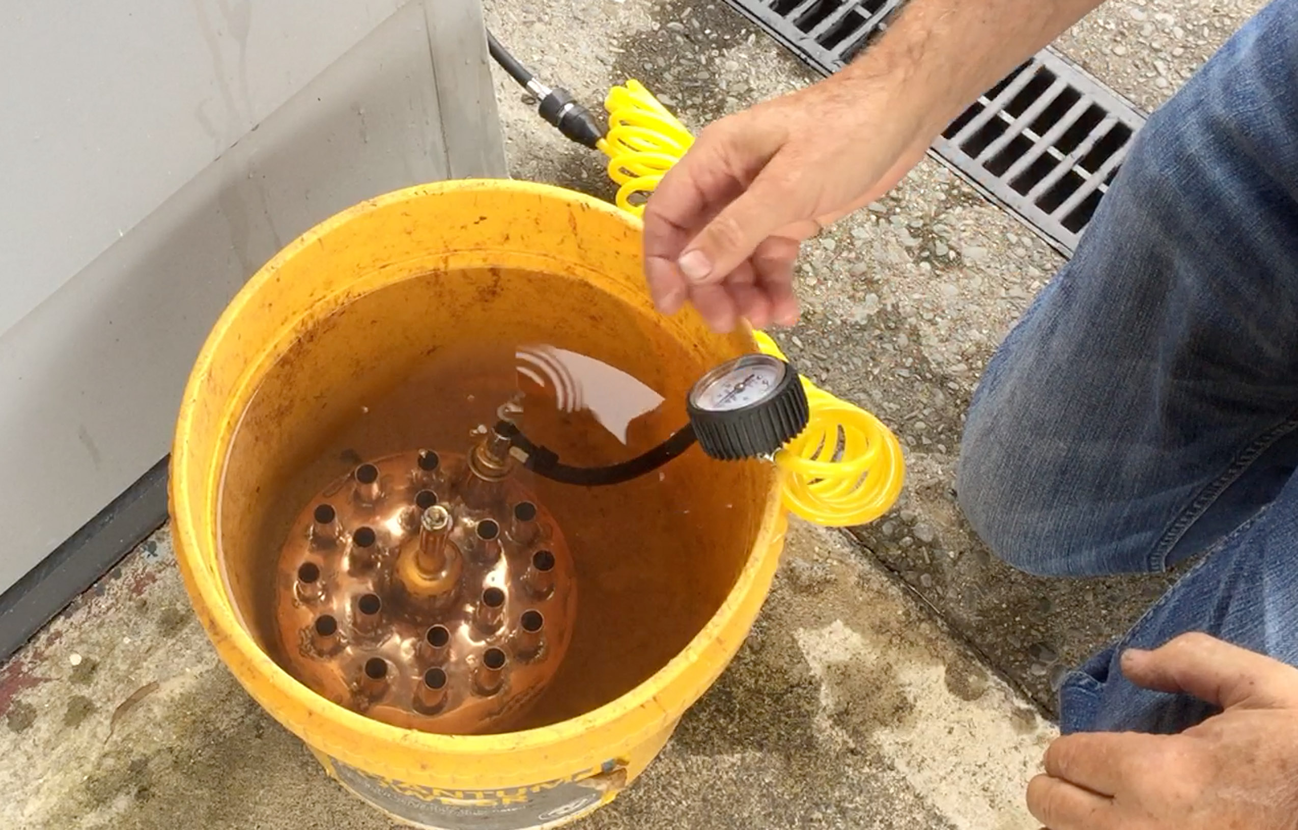
I only planned to operate the boiler at 15 pounds per square inch (psi) which is roughly equal to atmospheric pressure or one bar (actually 14.7 psi). However it is usual to test a boiler at about 4 times the operating pressure to give a good safety margin. I closed off all the vents, filled it with water and placed it in a bucket of water. Then I pumped it up to 125 psi which is 8.3 times the operating pressure. The tubes, which I brazed into the tank with silver solder, made it very rigid and it tolerated the pressure well. It included a dome shaped water trap similar to those used on the top of locomotives to prevent boiling water from going straight up the steam pipe. This can be a problem in small boilers where the water level is close to the steam outlet.
Since water is nearly non-compressible it does not store any energy when pressure is applied. Consequeently if the tank suddenly ruptured it would not cause a large explosion during testing. Air and steam are compressible and store a lot of energy and have the potential to cause a large explosion if the boiler ruptured. This explains why it is important to test the boiler under high pressure while full of water. I also immersed it in a bucket of water so that the energy of any rupture would be absorbed by the surrounding water.
Click to enlarge the photo
|
For pressure testing the new boiler it was filled with water, and immersed in water, before pumping the pressure up to 125 psi. |
The new high efficiency boiler was used with the original spinning rotor. I made the rotor used in versions 2 and 3 by spinning a flat copper disc in the lathe and pressing it onto a wooden mold or pattern until the copper was transformed into the shape of a bowl. (Several ornamental bowls were produced in the process.) Two bowls were joined together with a lip of copper holding them together and then they were soldered together. I had difficulty spinning the copper into a complete hemisphere so that a sphere could be produced, so I made this “flying saucer” shape instead. It should work just as well as a sphere. But it was mounted on a piece of copper pipe as an axle or shaft. Unfortunately this became slightly bent and at high speed it vibrated and caused the gear wheel to jump out of its thread.
Click to enlarge the photo
|
A close-up photo of the elliptical spinner of Hero's engine version 3 showing the way the copper edge of one bowl was wrapped over the second bowl before using lead/tin solder to join them. |
Click to enlarge the photo
|
The elliptical spinner after the joint was soldered. |
Click to enlarge the photo
|
Hero's engine version 3 after the improved boiler and crane had been added. |
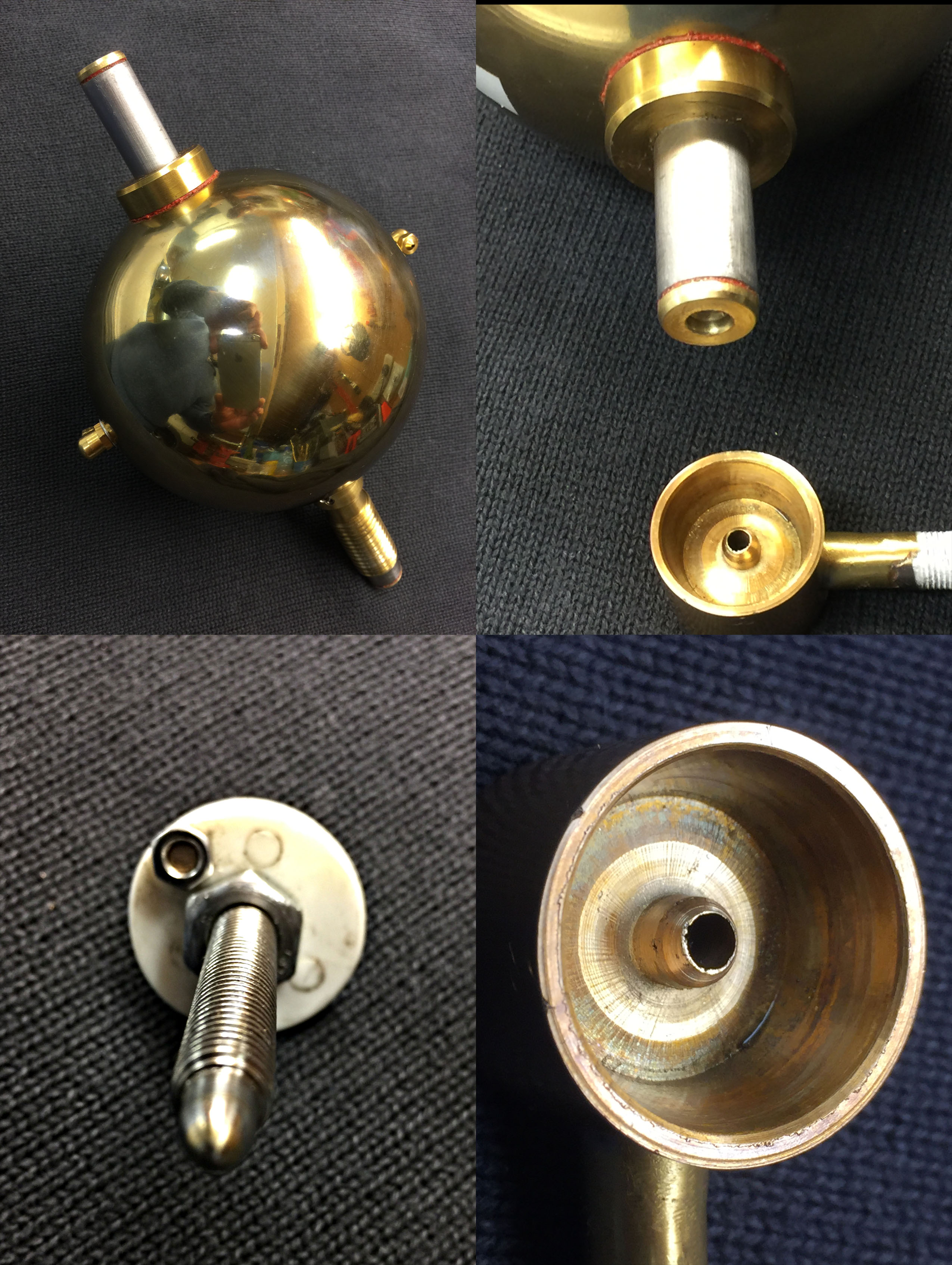
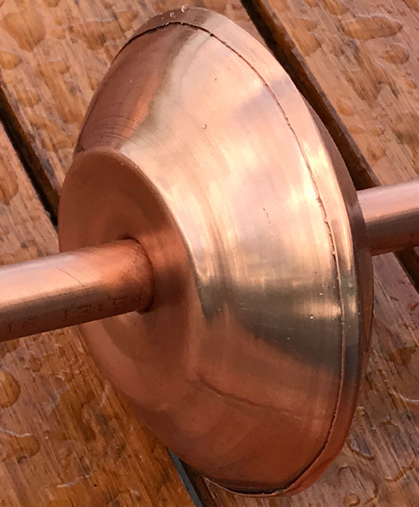
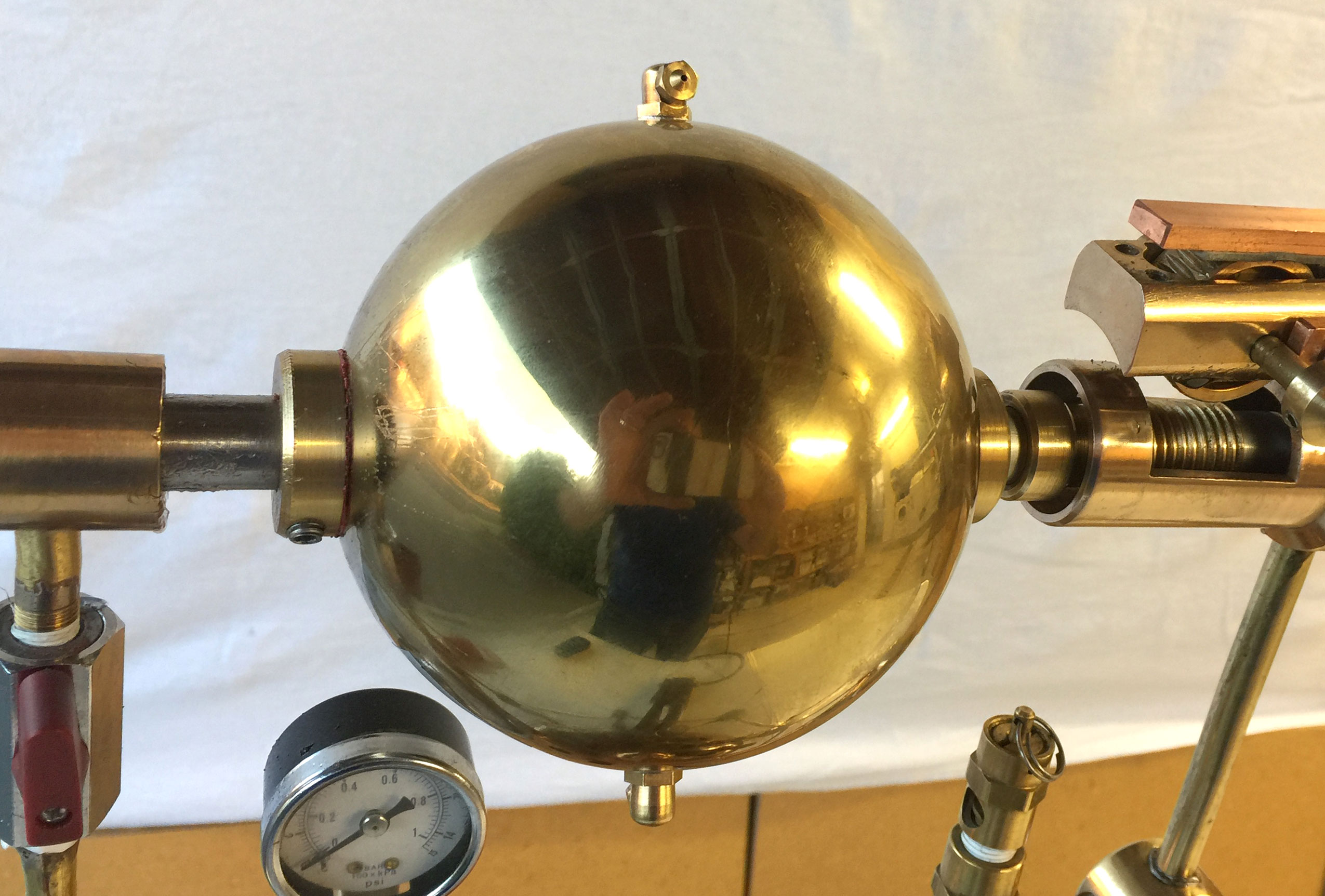
I purchased a light 120mm diameter stainless steel ball from China and made a rigid shaft out of solid stainless steel. I bored 10mm holes from each end of the 16 mm shaft to conduct steam and reduce the weight. (The thinly gold plated inexpensive spheres are used by the Chinese to produce a calming effect and perhaps see the future.)
Click to enlarge the photo
|
Version 4 with its gold plated sphere and improved boiler. |
Version 4 ran very smoothly with two 1 mm jets and reached a speed of 3500 RPM while lifting a load of 300 grams to a height of 500mm in about 15 seconds producing 0.1 Watts of mechanical energy. Without any load the speed increased to 5400 RPM measured by analyzing the sound track which showed 10,800 cycles per second as the two jets passed by. This was the highest speed and highest power output recorded.
Click to enlarge the photo
|
This sound track extracted from a video recording shows very clear oscillations as each jet passes by, confirming that it was spinning at a record speed of 5400 RPM - a record breaking speed. |
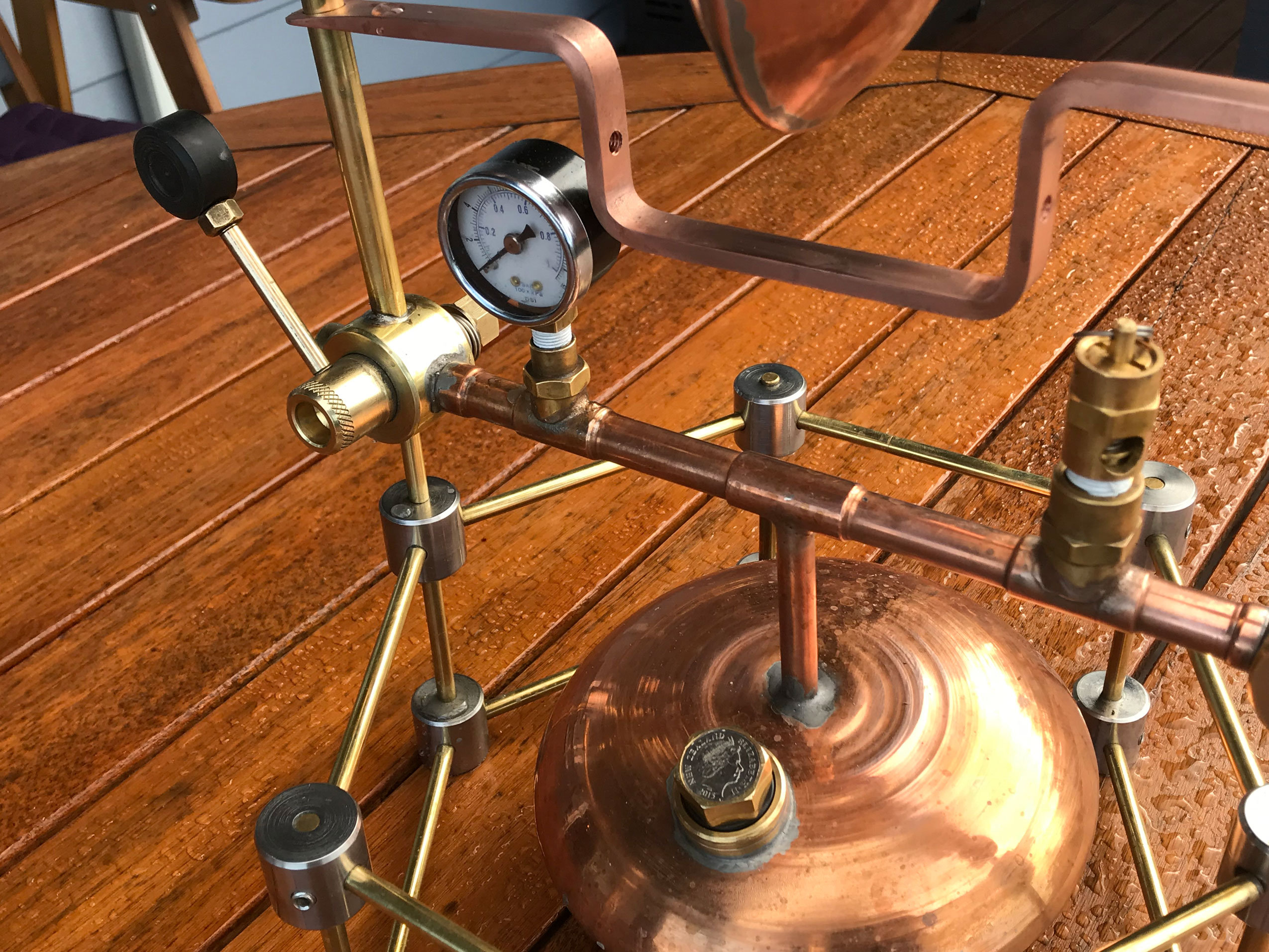
The boiler pressure was maintained so well that the pressure relief valve opened at 15 psi to release surplus steam pressure. This seems to be close to the upper limit of the speed that these machines can produce at this pressure, although bigger jets and even more steam production would, no doubt, produce more power.
My grandfather’s engine had jets made from welding tips. The holes where the steam escaped were about 2 mm in diameter. My versions 2 and 3 used grease nipples with the ball bearings removed which made jets 2.25mm diameter. These produced a lot of thrust when a pressure of 14 psi was applied but they used so much steam that the pressure from the small boiler dropped rapidly and the water ran out quickly.
In version 3 with the better boiler I did more experiments with smaller jets. I found that the nozzles used in 3D printers have the same 6mm threads as the grease nipples and by buying several of these I could drill them out to various jet sizes. The smallest size was 1/32 inch or 0.89mm. The engines ran well with this size and the steam pressure remained very high and when it reached 15 psi the pressure relief valve opened. The high pressure produced the highest RPM despite the small size of the jets. The next size was 1mm and that worked well too. 1.4mm worked, but ran at a slightly lower pressure and lower RPM.
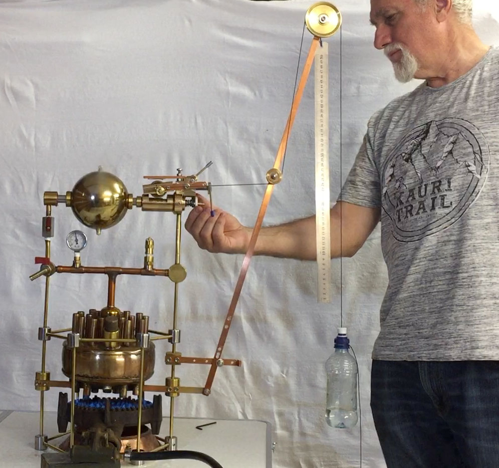
Many modern versions of Hero's engine have used spheres with jets placed on the tips of long arms. This is not a good idea because the arms moving through air at high speed suffer from air resistance. Since the sphere rotating does not have to displace air as it moves its air resistance is minimal and the jets should be placed near its surface. The rotor does not have to be a complete sphere but a cylinder or disk shape, ellipsoid or other shapes generated by rotation around the axis will work just as well because they do not displace air as they rotate. This is the advantage of using a sphere instead of pipes. Did the Greeks understand this concept too? They may have discovered by trial and error that this design gave the highest speeds.Well that is the burning question. We know that power output is proportional to the speed of rotation (Appendix B) so high speeds are desirable but must be geared down. Versions 3 and 4 were connected to the worm-drive gearbox which rotated a spool. String wound around the spool, was threaded over a pulley at the top of a crane and then to a plastic bottle containing water. (A second pulley was added half way up the crane to prevent the tension on the string from pulling the gear wheel out of its position in the worm gear thread.) The following power calculations are shown in Appendix A.
Version 3 with 0.89mm jets was able to lift 200 ml of water weighing 200 grams to a height of 500 mm in 18 seconds. The calculated power production was 0.055 Watts.
Version 4 lifted 300 grams 500mm in 15 seconds with a power of 0.1 Watts.
The circumference of the spool was 25mm and this rate of lift corresponds to 3000 RPM which is the same as I measured using a laser counter. Analysis of the sound track shows that version 4 was spinning at 5400 RPM with no load.
The circumference of the spool was increased from 25mm to 80mm and the height of the lift was increased from 500mm to 1170mm. Testing was started with 100 g of water in the bottle. It completed the lift in about 15 seconds which corresponds with power output of 0.078 Watts, just slightly less than earlier tests and the speed of lift corresponded with 2500 RPM which was a bit slower.

Click to enlarge the photo
|
Version 4 with the crane set up to measure how fast it could lift a bottle containing a known weight of water. The ruler is 0.5m long and the rate of rise is timed. |
Calculations reveal that the best power output was about 0.1 Watts. The fact remains that the engine did do some real work. The theoretical power which was calculated before the engine was built (Table 1 below) was 1.725 Watts which is 17 times more. It should have been able to lift this weight in about one second. The rate of lift was actually determined by the speed of rotation and gear ratios. Alternatively it should have been able to lift a weight 17 times heavier (3,400 grams), but heavier weights tended to slow it down, which results in less power output and as a result of this cycle it ultimately stops turning.
Efficiency of an engine is the amount of mechanical energy produced, divided by the amount of heat energy required to run it. This calculation produced low percentage efficiency for the Hero engines, but is this important? Is it even relevant if there is an unlimited supply of energy? After all, they only need to use a big boiler and put more wood on the fire until it produces enough steam to make the engine run. So efficiency may be irrelevant to its practical application, but it is of interest to compare it with modern machines.
When filled with 800 cc water it took 6 minutes to raise the temperature from 16C to boiling at 100C at atmospheric pressure. This works out to about 781 Watts being absorbed by the boiler (not including heat being lost into the air due to inefficiency of the boiler). This would suggest that the efficiency of the engine in converting thermal energy into mechanical energy is only 0.1 /781 x 100 = 0.0128% or less. For comparison steam locomotives were 7 to 11% efficient, petrol engines 30%, diesel 40% and gas turbines 37% efficient.
According to my theoretical calculations the thrust from the jets should not increase after they reach choke velocity and that should occur at 10 psi. However in practice the rotor did spin faster at higher pressures so it appears that my calculations may not be correct. It is therefore possible that if it operated at a higher steam pressure it could become more efficient, but I think the Greeks would not have been able to produce steam boilers producing pressures much higher than 15 psi. The production of boilers that could handle higher pressures was a limiting factor in early steam engine designs in the 18th century (see my video in the history of steam engines below.)
In order to calculate the power it was necessary to calculate the torque from the thrust produced by steam escaping from each of the two jets (Appendix B). The maximum velocity of gas traveling through a jet cannot exceed the speed of sound at the temperature and pressure within the jets (377 m/s). Although I expected the steam pressure required to reach the speed of sound would be very high, I was surprised to find that my calculations suggested it would occur at about 10 psi. That is one of the reasons why I designed the machine to work at 10-15 psi.
If we assume that the steam does reach the speed of sound it makes it relatively easy to calculate what mass is being ejected through the jets every second. Newtons third law then allows us to calculate the thrust. Multiplying the thrust by the radius of the sphere gives the torque produced. Multiplying torque by the speed of rotation in revolutions per second gives us the power being produced in Watts. From the mass being ejected through the nozzles it is also possible to calculate how much water is consumed per second and how long 500ml of water would last. All of these numbers vary with the size of the jets being used. The theoretical calculations are shown in the following table.
The efficiency is always 1.5%. The fact that it does not vary in this table is not a coincidence. The power output is determined by the thrust produced by the jets and that is calculated fom the weight of steam being ejected per second. Consequently the amount of water used is propotional to the thrust. The amount of energy needed to heat that water is also proportional to the thrust. When efficiency is calculated by dividing power output by power used by the boiler the ratio is always the same.
However, in this table it was assumed that the speed of rotation was always 3000 RPM. If the speed were doubled with the same thrust and torque, the power output would be doubled and efficiency would increase to 3%.
| Jet diameter | Thrust | Power produced | Water used | 500cc water lasts | Power used* | Efficiency |
| mm | Newtons | Watts | grams/second | minutes | Watts* | % |
| 2.25 | 0.475 | 16.0 | 2.52 | 3.3 | 1063 | 1.5 |
| 1.5 | 0.259 | 8.72 | 1.376 | 6 | 580 | 1.5 |
| 1.0 | 0.090 | 3.03 | 0.48 | 17.5 | 202.5 | 1.5 |
| 0.89 | 0.0512 | 1.725 | 0.272 | 30 | 114.8 | 1.5 |
* The amount of energy required to boil water is 422 Joules per gram.
However, the results actually obtained by measuring how fast it could lift a weight were much lower. The reason is not entirely clear. Energy loss through friction in the bearings and due to air resistance would play a role. It was also observed that the RPM kept increasing as the pressure increased from 10 to 15 psi. This would suggest that the upper limit of thrust had not been reached.
My design includes a pressure gauge that shows 0-15 psi and a pressure relief valve which opens to release steam if the pressure goes over 15 psi. In this version I made a single 'stop-cock' valve that could direct the steam up to the rotor, out to an exhaust vent, or close it off completely. Unfortunately it bucked when heated for soldering and was replaced with two commercially available valves, one for the exhast vent and one to open the pipe to the spinning rotor.
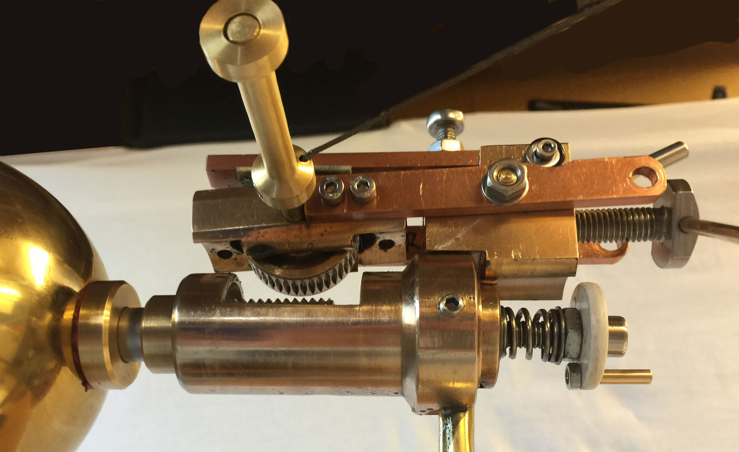
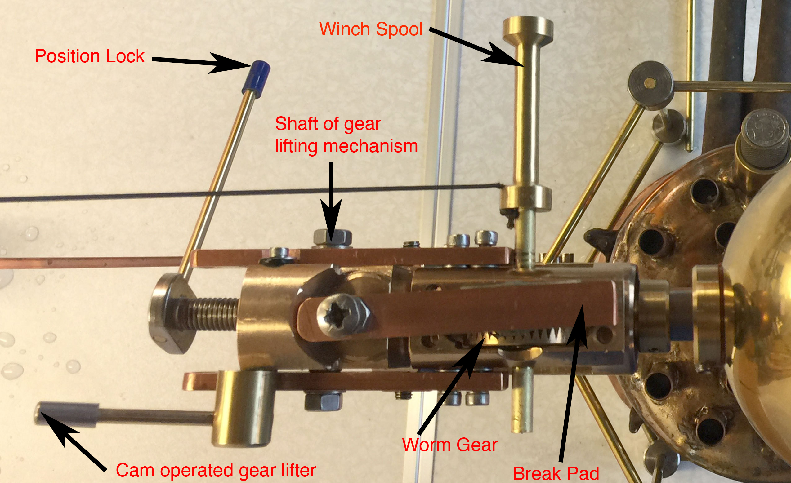
The original gearbox was designed to rotate so that the output shaft could be tilted down to an angle of 45 degrees to drive an Archimedes screw intended to demonstrate pumping power (above). However, it was modified later to operate a small crane instead, as it would be easier to test varying loads. This required a mechanism for engaging and disengaging the gear by lowering the gear wheel into the thread or raising it out of the thread. This was achieved by mounting the gear carrier frame on a shaft so that it could be tilted by a cam on the back of the unit. Whenever the gear wheel was moved it could be locked into position by a long lever that clamped the shaft.
A strip of copper bar above the gear wheel has a brake pad on its under-side so that if the gear is raised up high it presses on the pad and prevents the spool from turning, and prevents the weight from dropping.
Under this mechanism there is a small white wheel with a brass handle on it. This is the right hand pivot that the main shaft rotates upon. The tip was originally cone shaped but changed to a spherical shape. It is threaded (actually a stainless steel screw) and can be screwed in and out by turning the white knob as seen in the photo with the operator turning the knob. The spring creates friction and stops it from unwinding on its own. The spool for winding the string on the crane has a circumference of 25 mm.
Click to enlarge the photo
|
A front view of the gearbox on version 4. |
Click to enlarge the photo
|
The plan view of the gearbox and gear engagement mechanism with parts labeled. |
Click to enlarge the photo
|
The Hero engine with the crane actually lifting a bottle containing 100 grams of water. The small winch spool has a circumference of 25mm. |

|
Click to enlarge the photo
|
The gear engagement mechanism after removal from the Hero's engine. |

Click to enlarge the photo
|
The gear engagement mechanism removed from the Hero's engine. The blue lever is mounted on the head of a screw which clamps against the shaft, locking the gear engagement into any position. |

Click to enlarge the photo
|
Underside of the gear engagement mechanism removed from the Hero's engine. The cam at the bottom right is operated by the silver lever and raises the arm by pressing against the copper bar. |

Click to enlarge the photo
|
The thread of the worm drive after removal of the gear engagement mechanism from the Hero's engine. |

Click to enlarge the photo
|
Back view of the rotor mechanism. The white knob is for adjusting the pressure applied to the pivots. |

Click to enlarge the photo
|
The gear mechanism with the gear engaged in the screw thread. The shaft through the gear wheel turns the winch spool to wind in the string and lift the weight. |

Click to enlarge the photo
|
The worm gear in this image is disengaged and in the braking position. |
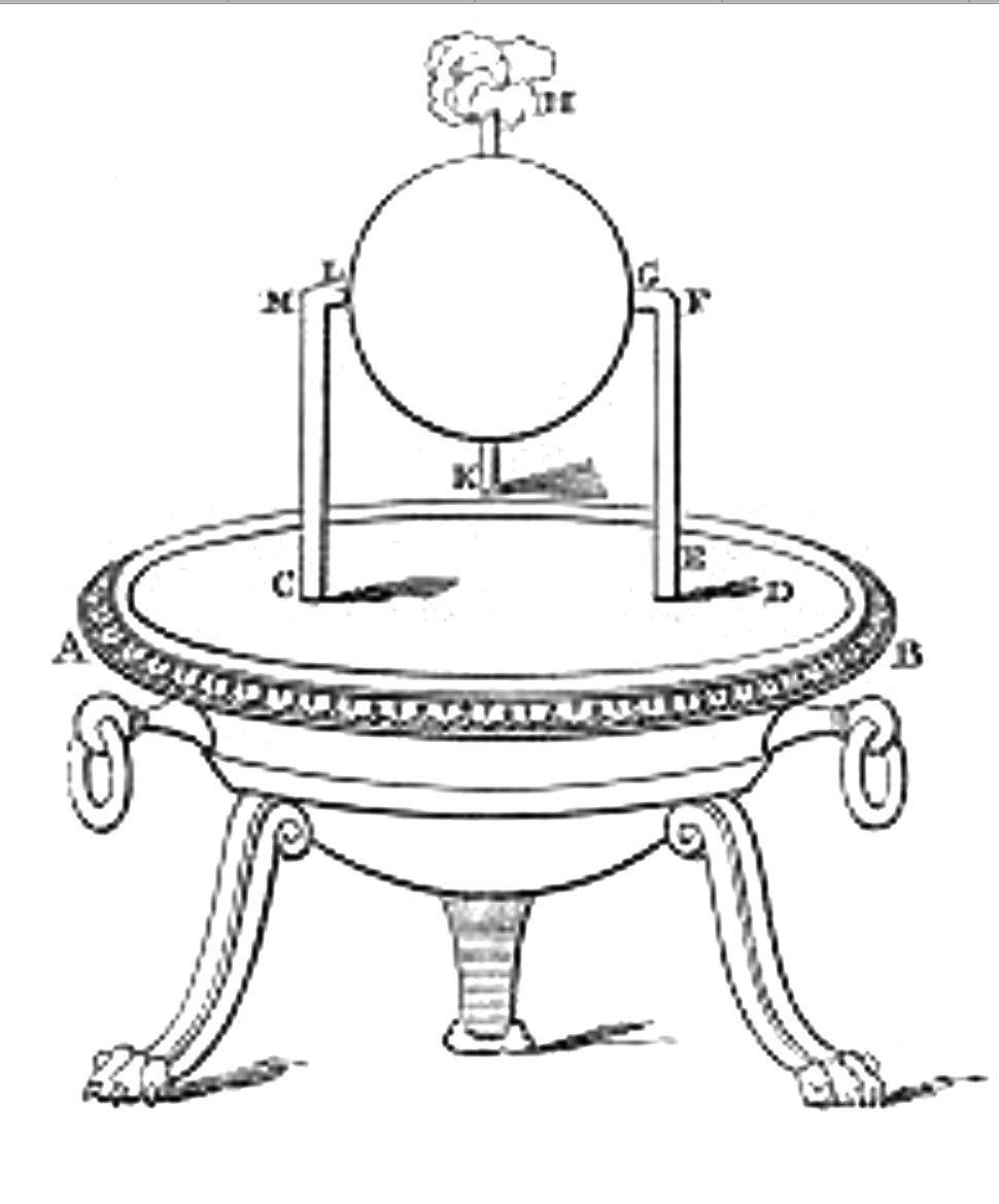
From the English translation by Woodcroft (a).
PLACE a cauldron over a fire: a ball shall revolve on a pivot. A fire is lighted under a cauldron, A B, (fig. 50), containing water, and covered at the mouth by the lid C D; with this the bent tube E F G communicates, the extremity of the tube being fitted into a hollow ball, H K. Opposite to the extremity G place a pivot, L M, resting on the lid C D; and let the ball contain two bent pipes, communicating with it at the opposite extremities of a diameter, and bent in opposite directions, the bends being at right angles and across the lines F G, L M. As the cauldron gets hot it will be found that the steam, entering the ball through E F G, passes out through the bent tubes towards the lid, and causes the ball to revolve, as in the case of the dancing figures.

Click to enlarge the photo
|
This etching of Hero's steam engine is not from his original manuscript which has been lost. It was probably produced in the middle ages. It shows steam forced out of the jets causing the sphere to rotate. It is heated by a fire. Letters on the diagram match those in Hero's written description. |
Click to enlarge the photo
|
Another etching of Hero's steam engine also probably dates back to the middle ages. |

Click to enlarge the photo
|
A third, more elaborate, etching of Hero's steam engine. The shape of the pivot is clearly shown. It is heated by a fire and in this case there is an image of a man holding the fire under the cauldron which is supported by pedistals in the image of lions. |
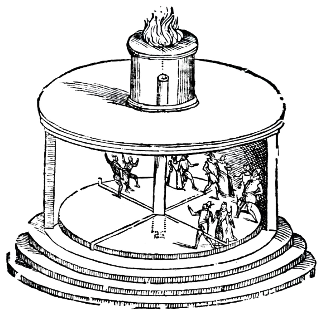
Number 70 in Hero’s list of designs in Pneumatica was called “Figures made to dance by fire on an alter”. This worked on the same principal as Hero’s steam engine, but instead of using steam he used air escaping from a chamber as it heated up and expanded. The jets were mounted on the floor of a rotating stage with figures of people dancing mounted on it. Unfortunately in this drawing, most likely from a later manuscript, the jets appear to be pointing straight up or straight down. They should remain in the same plane as the stage floor and tangential to the edge of the floor. Here is Hero's description taken from the English translation (a,o).
WHEN a fire is kindled on an altar, figures shall be seen to dance: for the altars must be transparent, either of glass or horn. Through the hearth of the altar (fig. 70), a tube is let down turning on a pivot towards the base of the altar, and, above, on a small pipe which is attached to the hearth. Communicating with, and attached to, this tube are smaller tubes lying at right angles to each other, and bent at the extremities in opposite directions. A wheel or platform on which the dancing figures stand, is also fastened to the tube. When the sacrifice is kindled, the air, growing hot, will pass through the pipe into the tube, and be forced out of this into the smaller tubes; when, meeting with resistance from the sides of the altar, it will cause the tube and the dancing figures to revolve.
Click to enlarge the photo
|
A woodcut etching of Hero's dancing figures. This works on the same principal as Hero's steam engine but uses heated air (instead of steam) escaping from jets at the edges of the dance floor to make it rotate. The jets appear to be drawn at the wrong angles.They should be in the same plane as the dance floor at a tangent to the floor. (From Wikipedia.) |
We consider engines today to be machines providing mechanical power to relieve mankind from manual work. But that was not the intention of the people who developed the aeolipile. They considered it a scientific experiment. It has been claimed that Hero’s engine was used to perform useful work, but these turn out to be incorrect. This is of particular interest because if Hero’s machine had been recognized as a useful engine it could have been developed and may have led to more powerful engines resulting in an industrial revolution 2000 years ago. Instead it seems to have been treated as a novelty or curiosity for centuries.
It was astonishing to read in the Wikipedia article a quote from Mokyre (g)
and another quote from Wood (h)
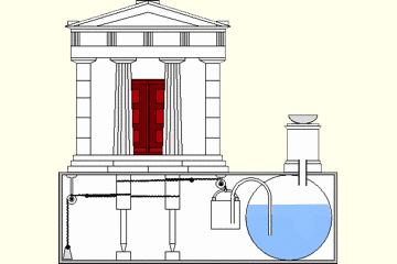
These quotes are clearly a confounding of two of Hero’s devices, as the Wikipedia article pointed out. Pneumatica (a) did include a machine which opened temple doors but it did not use Hero’s steam engine or aeolipile. This is how the temple doors were opened:
In the temple there was an alter where a fire could be lit. As it burned it heated air in the chamber under the alter. The door hinges were connected to poles in a chamber underneath the temple and the increasing air pressure from the alter was transferred by a tube into the chamber where it was connected to an enclosed vessel full of water. The pressure caused the water to be pushed out of the vessel into another open vessel or bucket which was connected to ropes wrapped around the poles. The bucket falling caused the poles to rotate and the doors to open. When the fire went out, the cooling caused the whole process to be reversed and the doors closed.
Click on the animated GIF below. It was found on a web site by Lahanas (n) but the original source for several of the images he used appears to have been lost as broken links. He said it is an animated image by P. Hausladen, RS Vöhringen from Neu Ulm in Germany. I have revised the GIF as described in the caption.
Click to view the GIF on its own
|
An animation showing Hero's mechanism for opening temple doors when a file was lit on an alter. It has been modified by using the red color to indicate that the air was being heated by a fire. It shows that as the air expanded, the air pressure increased, forcing water out of the reservoir into a bucket. As the weight of the bucket increased it opened the temple doors. It now shows the temple doors closing automatically when the fire goes out. From Lahanas (n). This mechanism has been confused with Hero's engine. |
It has also been frequently claimed that Hero’s engine was used by Taqī Ad-Dīn in 1551 to turn meat on a spit (k). But this is also incorrect. The device he described used steam jets directed at vanes placed on the periphery of a wheel (m). This is known as an impact steam turbine. (The device for adjusting the height of cooking vessels over a file was known as a jack and the steam driven spit was called a steam jack. The life of Taqī Ad-Dīn is described by Sevim Tekeli (l) and mentions that he was born in Damascus in 1521.)
The question of whether the Hero engine could perform any useful work remained unanswered until today.
Woodcroft (a) states in his introduction to the Greek translation that Hero says his books are a compilation of information from other philosophers with the addition of some of his own ideas, but he does not specify which ideas are his own. In the case of the aeolipile steam engine he referred to previous writings by a Roman author, Marcus Vitruvius Pollio (referred to as Vetruvius), who described a machine like the aeolipile in De Architectura (f) about 100 years earlier (He lived about 80 BCE to 15 CE). However, Vitruvius did not give sufficient detail or drawings to confirm that he was writing about the same device but he did state its name. He did not mention any moving parts and he seems to be describing a simple steam boiler:
Aeolipilae are hollow brazen vessels, which have an opening or mouth of small size, by means of which they can be filled with water. Prior to the water being heated over the fire, but little wind is emitted. As soon, however, as the water begins to boil, a violent wind issues forth (f).
Hero frequently refers to the work of the Ctesibius (285-222 BCE), sometimes spelled Ktesibios or Tesibius, and for many years it was thought that Hero was his student in Alexandria. However it is now thought that Hero was alive almost 300 years later in 63 CE.
The word Aeolipile means the “Ball of Aeolus” and Aeolus (in Greek Αἴολος) was the Greek god of wind and air. Pila is the Roman word for ball. It is sometimes spelled aeolipyle or eolipile.
Vetruvius (f) described the aeolipile as a
“scientific invention [used to] discover a devine truth lurking in the laws of the heavens… Thus from this slight and very short experiment we may understand and judge the mighty and wonderful laws of the heavens and the nature of winds.”
It seems clear that he was describing a scientific experiment rather than inventing a machine or engine.
Interestingly they did. The Greeks not only knew about the use of gears and pulleys but could also carry out all kinds of metal work. An Australian engineer Chris Ramsay (r) noted the presence of solder in x-rays of the Antikythera computer (u), and has produced a fascinating series of YouTube videos showing how they might have built this device, including joining it together with an alloy of tin and lead, known today as solder (modern solder also contains antimony).
The Greeks even had lathes. About 100 years before Hero the Roman engineer, Vetruvius, described a lathe. This consisted of a string wrapped around a shaft so that as the string was pulled alternately up and down it caused the shaft to rotate alternately clockwise and anti-clockwise. It was pedal operated with a foot pedal pulling the string down against a spring loaded lever that pulled the string back up. A tool was supported on a platform to cut material from the surface of any material (metal or wood) attached to the rotating shaft. A translation of the description by Vesuvius follows:
Machine for the finishing of metal or wooden objects giving form on a surface by their rotation with matter removal. The upper end of the rope wrapping the object was attached to a flexible yet stable horizontal rod, and the lowest end was attached to a foot powered axle. The finished metal or wooden object rotated counter-clockwise with pressing of the foot pedal by the craftsman, and then clockwise by the restoring force of the rod. The cutting tool, based on the front horizontal bar, was applied over the rotating piece.
The image below is a photo taken by Augusta Stylianou of a model made by students and described by Lahanas, in References (o) to (u), as from an "Ancient Greek Technology" exhibition at the Evagoras & Kathleen Lanitis Centre in Carob Mill Limassol, [showing] Replicas and Reconstruction by Prof. Kostas Kotsanas and his students.
A BBC documentary recently showed a similar technique which they think was used 4000 years ago in Dartmore to make wooden ear rings which clealy have turning marks on them. The Greek lathe reminds me of the tiny lathe my grandfather used in his car shed with a dirt floor. It used the pedal mechanism of a modified Singer sewing machine which could spin the work constantly in one direction. His sheds contained several old Edison cylinder phonographs which were themselves like lathes with leadscrews.
.jpg)
Click to enlarge the photo
|
This model of a pedal operated lathe, thought to be used by ancient Greeks, was made by students of Professor Kostas Kotsanas, photographed by Augusta Stylianou, and used in a web site by Lahanas. The pedal makes the work rotate alternately clockwise and counterclockwise. |
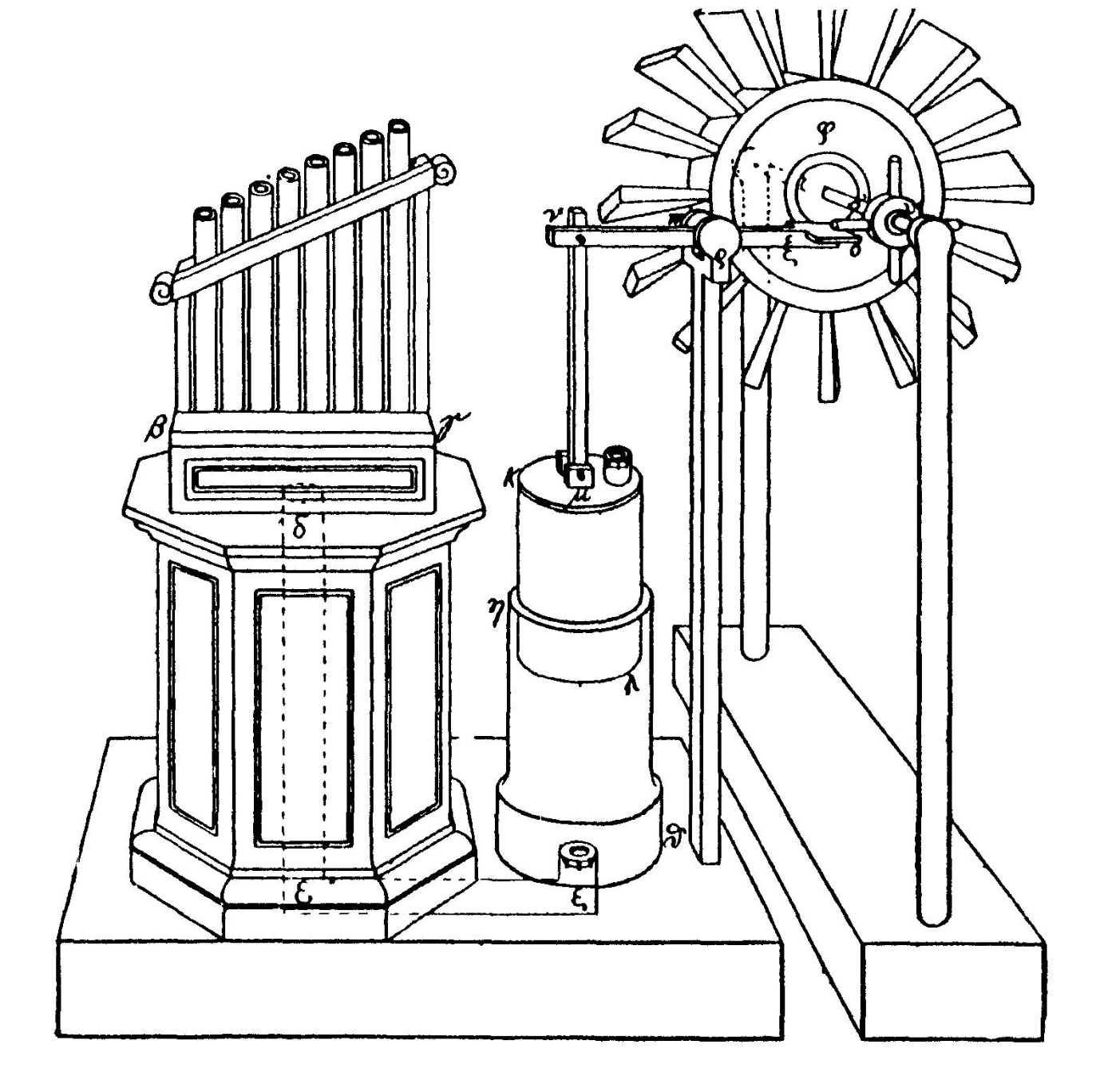
Another invention described by Hero was the Wind Organ. This included a piston pump driven by a windmill. The piston pump had already been attributed to Aristotle who died in 212 BCE nearly 300 years before Hero. Hero also described an hypodermic syringe for medical use. He was very familiar with the concept of pistons and could have been very close to inventing a steam engine using pistons.
Click to enlarge the photo
|
Hero's wind organ consists of a small windmill driving a piston pump connected to a pipe organ. With this knowledge of steam and pistons he was tantelizingly close to inventing a piston operated steam engine. |
In fact scholars in Mediteranian and Arabic states throughout the middle ages studied the Greek scientific literature, including Hero, and it is surprising that no-one put these ideas together. It is thought that the reason is, not the lack of knowledge, but a belief that such things were not needed. In fact it was felt to be dangerous to introduce labor-saving machines when most of the population were slaves who could revolt if set free from labor.
Emphatically yes! The best example is the Antikythera which is considered to be the first known analogue computer. It was used to very accurately predict the movement of all the bodies in the known universe at the time and could predict eclipses of the sun and moon. It was found in a ship wreck in 1901 and x-ray’s reveal that it is made up of dozens of intricate intermeshing gear wheels and levers, much more complicated than a mechanical watch or clock. The engineering skill in building this device is very impressive and involved soldering as well as gear making. It has been argued (w) that they did not have the advantages of modern gear design to reduce friction and handle heavy loads, and yet they did have a design for lifting heavy weights with gears. Perhaps we tend to be a bit arrogant but engineers say it is doubtful that this design with triangular gears rather than the involute curves of modern gears could handle heavy loads.
The astronomy and mathematical knowledge required to build the Antikyther is equally complex and may date back to work done by the Babelonians. It’s mechanism has been found to work on dates from 205 BCE and that is thought to be the date of manufacture as well (s). Interestingly that coincides with the life of Archimedes who was killed when the Romans invaded Syracuse in 212 BCE, and he may be the inventor of the Antikythera. It is thought that he did design other similar objects. However he did not personally write about any of his work.
Hero also described an odometer in his book Dioptra (n) for measuring the distance that a cart traveled by road and this utilized worm gears. It was also described by Vetruvius and may have been invented by Archimedes. The Roman mile was 5000 feet. (The British changed their definition of a mile to 5280 feet so that it could be divided into furlongs which was their preferred measurement of land.) Interestingly a wheel 4 feet in diameter revolving 400 times measured 5026.5 feet which was considered to be close enough to a Roman mile. The wheel had a peg that tripped a pegged gear wheel to move by one peg each time the wheel rotated. The gear wheel was attached to a worm gear mechanism which drove another shaft, which drove three more worm gears and shafts in series. The final, geared down shaft rotated a horizontal disc with many holes containing stones. When the disk rotated and one of these holes lined up with a stationary hole, a stone dropped through the hole into a container. At the end of the journey the number of miles traveled was equal to the number of stones in the container.
.jpg)
Click to enlarge the photo
|
A sketch of an odometer following the design of Hero and others. It could measure how many miles the cart had traveled. (From Lahanas (n)). |
.jpg)
Click to enlarge the photo
|
Another sketch of Hero's odometer showing four worm gears in series (From Lahanas (n). |
Another device called the Baroulkos (q) designed for lifting heavy weights was described by Hero and has been reviewed in an article in Scientific American (p). It was operated by a crank which turned a worm gear, which then turned a series of four pairs of gear wheels to reduce the speed of rotation and this increase torque. The last gear was connected to a spool and rope to lift the weight. This, or a similar device, could have easily been connected to a Hero’s steam engine. In fact, my design with a worm gear parallels the design of the Baroulkos and odometers.
.gif)
Click to enlarge the photo
|
A mechanical gear reduction winch known as a Baroulkos with 4 sets of gears with two gear wheels in each stage and driven by a worm gear. (From Lahanas(n)). |
Heros two-volume work Pneumatica was all about devices and inventions based on behaviour of gasses, air and steam. The English translation of Hero’s Treastise on pneumatics (a) gives a wonderful description of how air can be compressed. Considering that it was nearly 2000 years before Boyle developed his gas law describing the relationship between pressure, volume and temperature and the modern understanding of atoms and molecules, this text is amazing. There was a controversy in the time of Hero about whether vacuum really exists. At the time they thought of air, earth fire and water as the primary elements of nature. There was a group who thought that all matter consisted of tiny indivisible particles which they called atoms. Hero apparently agreed with these 'atomists'.
Now the air, as those who have treated of physics are agreed, is composed of particles minute and light, and for the most part invisible. If, then, we pour water into an apparently empty vessel, air will leave the vessel proportioned in quantity to the water which enters it. This may be seen from the following experiment. Let the vessel which seems to be empty be inverted, and, being carefully kept upright, pressed down into water ; the water will not enter it even though it, it be entirely immersed : so that it is manifest that the air, being matter, and having itself filled all the space in the vessel, does not allow the water to enter. Now, if we bore [a hole in] the bottom of the vessel, the water will enter through the mouth, but the air will escape through the hole… Hence it must be assumed that the air is matter. The air when set in motion becomes wind, (for wind is nothing else but air in motion), and if, when the bottom of the vessel has been pierced and the water is entering, we place the hand over the hole, we shall feel the wind escaping from the vessel ; and this is nothing else but the air which is being driven out by the water. It is not then to be supposed that there exists in nature a distinct and continuous vacuum, but that it is distributed in small measures through air and liquid and all other bodies. …The particles of the air are in contact with each other, yet they do not fit closely in every part, but void spaces are left between them, as in the sand on the sea shore: the grains of sand must be imagined to correspond to the particles of air, and the air between the grains of sand to the void spaces between the particles of air. Hence, when any force is applied to it, the air is compressed, and, contrary to its nature, falls into the vacant spaces from the pressure exerted on its particles: but when the force is withdrawn, the air returns again to its former position from the elasticity of its particles,… bodies will have a rapid motion through a vacuum, where there is nothing to obstruct or repel them, until they are in contact. Thus, if a light vessel with a narrow mouth be taken and applied to the lips, and the air be sucked out and discharged, the vessel will be suspended from the lips, the vacuum drawing the flesh towards it that the exhausted space may he filled. It is manifest from this that there was a continuous vacuum in the vessel.
At the time of the translation of Hero’s two books called ’Pneumatica’ by Bennet Woodcroft in 1851 it was not known when he lived. It was thought that he had been a pupil of Ctesibius of Alexandria which would place him in about 150 BC to 270 BC and these dates are sometimes quoted even today. But Hero’s most important work on geometry ‘Mechanica’ was lost until 1896 and according to Encyclopedia Britanica it wasn’t until 1949 that it was revealed by Boas that Hero reported in his book ‘Dioptra’ an eclipse of the moon on March 13th 63 CE (most modern texts say 62 CE).
It is now assumed that he was alive at the time of that eclipse and might been born about 10-20 CE and would have died about 70-100 CE, but it is possible that he lived some time later. Hero was interested in the local time recorded for an eclipse in Alexandria and Rome so that he could describe how to calculate the distance between the two cities based on spherical geometry. The actual data was less important than the method he was describing, and Sidoli (c) quotes Hero as saying:
“Now, let the same lunar eclipse have been observed at Alexandria and Rome. If one is found in the records, we will use that, or, if not, it will be possible for us to state our own observations because lunar eclipses occur at 5- and 6-month intervals.”
No-one really knows. The drawing universally used to depict Hero was in fact created by a German artist in the 1700’s. It appears to be purely an artists impression of what a Greek philosopher should look like (t,n). Claims that his parents moved from Greece to Egypt in 10CE is pure conjecture based on historical events which occurred about the time of his estimated date of birth.
Click to enlarge the photo
|
A drawing that has been used since the 1700s to show what Hero might have looked like Actually there is no description of him in the literature. |
Hero or ‘Heron of Alexandria’ is considered a philosopher and polymath which means he was skilled in many different fields of study, but today we would probably call him an engineer or scientist. He lived in Alexandria on the northern coast of Egypt, but Alexandria at the time was under Roman rule after being annexed by the Romans. Roman influence in Egypt dates back to 3500 CBE.
Hero wrote in Greek and is therefore described as Greek, but since most of the previous literature had been written in Greek he would have to be able to read and write in Greek. That doesn’t necessarily mean that he was of Greek ethnic origins. Woodcroft in 1851 pointed out that there was no mention of his origins in the literature and no description of his appearance. Greek was commonly spoken in Rome. Today English is the language used in most scientific literature but just because a scientist publishes in English does not mean that he is from England. Similarly Latin used to be the common language for academics, but does not have anything to do with ethnic origins.
It is thought that he would have studied and later taught in the Mouseion (Museum) associated with the Temple of Serapis or the Serapion which was the Temple of the nine Muses (d). The Muses were Greek godesses, the nine daughters of Zeus, who promoted nine branches of the arts, but are now considered to support all learning and study. This temple was actually more like a modern university campus (e) and included the Great Library of Alexandria which contained huge numbers of scrolls and documents of the ancient world. Unfortunately the library was later destroyed by fire. It is thought that Hero’s many books were actually collections of lecture notes that he used for teaching. Alexandria is a city on the Mediteranean coast of Egypt founded in 331 BCE by Alexander the Great when it was taken over by Rome. It is particularly famous as the place where Pharos resided, for the Great Library of Alexandria and an ancient lighthouse.
Hero wrote at least a dozen major works and the aeolipile was the 50th of 78 devices or inventions mentioned in his treatisse 'Pneumatica'. Copies of Hero’s works were the most important scientific books read throughout the middle ages. About a 100 copies of Pneumatica are known to exist in various translations but the oldest was produced in about the 13th century. It is known as Codex Gr.516 and is held in the Bibliotheca Marciana in Venice (i).
The first full version produced by a printing press was the Latin translation by Frederico Commandino in 1575 and soon after that there was a version printed in Italian by Bernadino Baldi in 1579 (i). A paraphrased version of the beginning of Pneumatica had been printed in Venice in 1501 by Valla (i).
When Woodcroft (a) prepared his English translation he had many versions in Latin and Italian to compare with the copy of a Greek manuscript. Each of these included drawings and in his translation he used the best drawings available or drew his own. So although it is said to be an English translation of the original Greek manuscript, he actually only had a copy of the original produced by hand and it included obvious copying errors. He had to suplement it with information and drawings reproduced in many different translations and copies.
URL links can be clicked to find the reference online in most cases.
In these short YouTube videos I am using the engineer's lathe to make all the parts for the Hero Steam Engine. It includes several special techniques such as spinning copper into a bowl shape from a flat sheet, and making the gear wheel for the worm drive gear box. The methods apply to any engineering lathe. The model I am using is a 1953 Boxford Model A.