 |
|
|
|
|
|
|
|
|
|
|
|
|
|
|
|
|
|
|
|
|
|
|
|
|
|
|
|
|
|
|
|
|
|
|
|
|
|
|
|
|
|
|
|
|
|
|
|
|
|
|
|
|
|
|
|
|
|
|
|
|
|
|
|
|
|
|
|
|
|
|
|
|
|
|
|
|
|
|
|
|
|
|
|
|
E-Mail Tony@lathes.co.uk
Home Machine Tool Archive Machine Tools For Sale & Wanted
Machine Tool Manuals Machine Tool Catalogues Belts
"Selig Sonnenthal"
Machine Tools
Selig Lathes Page 1 Selig Lathes Page 2 (The Sundale)
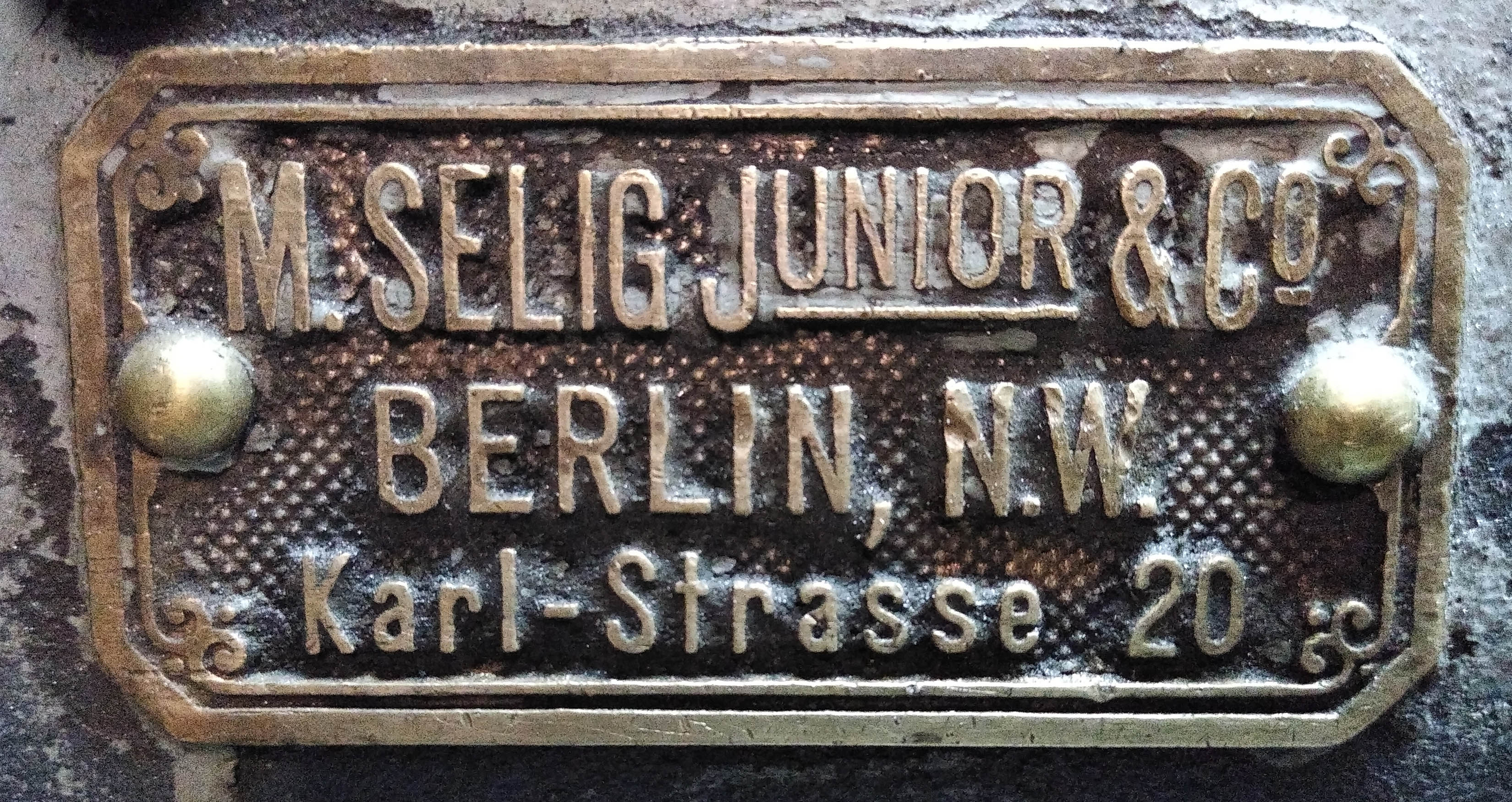
Founded in Victorian England during 1871, the Selig Sonnenthal company were originally known as M. Selig Junior & Co. and based at Lambeth Hill, Queen Victoria Street, London S.E.. As well as being manufacturers with a factory in Coventry, they were also very successful agents (various maker's and branding badges are found on their machine tools), importers and one of the leading retailers of engineering and associated products. They described themselves (during the period 1880 to 1910) as: importers of American & other foreign engineers' tools & machinery wholesale & export, hardware & machinery merchants & contractors for metal & railway materials of every description. Eventually, using the first three letters from each name, they took on a new and easier-to-market identity as Selson - a company that was to became a considerable force in machine-tool marketing and, in turn, the foundation of the large "600" engineering group. Amongst the first machine tools they handled was a wide range of lathes - from simple, lightweight plain-turning types to heaver, backgeared and screwcutting models for the repair workshop - and a variety of shapers and planers. These would have been provided from their own works as well as a number of contemporary English, European and American makers - and all appear to have been of better-than-average quality.
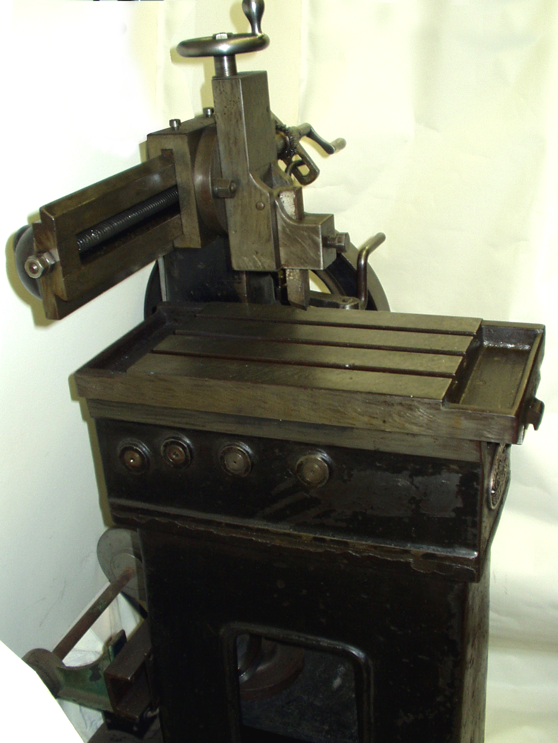
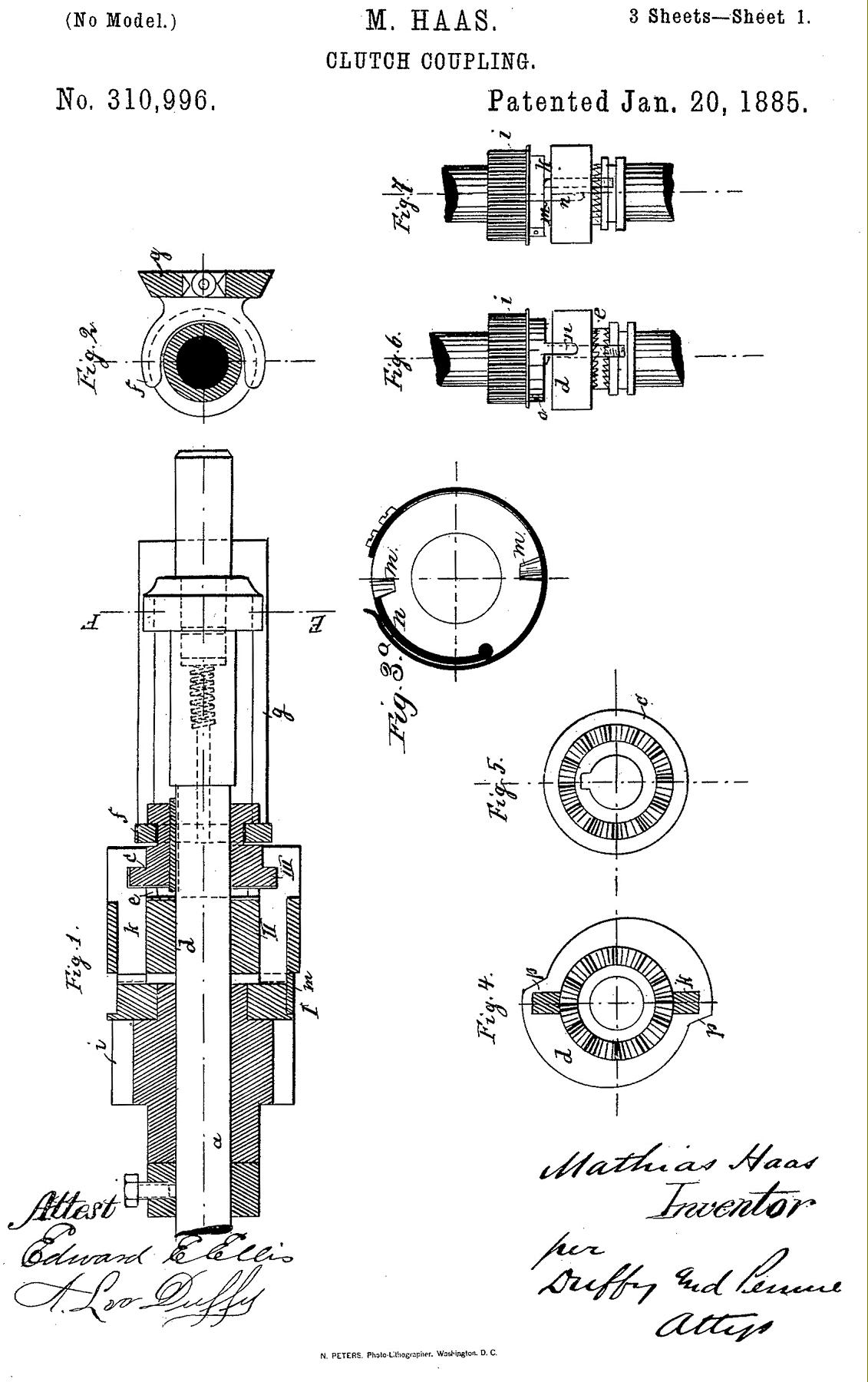
Shown below is an interesting small "open-sided" planer, almost certainly German in origin; the oil holes are marked 'Oel' and parts of the table drive mechanism are stamped M.Hass Patent* (this aspect of the design was an important of the machine - and it even drew comments in the English Mechanic & World of Science, 1887 where it was described as the Eureka (Hass' patent). In response to a reader's enquiry the reply stated: 61211 Planing Machine. You can't make your planer like the so-called Eureka (Haas' patent) because the clutches are, firstly, patented and secondly-difficult to make).
Motorised, with a countershaft bolted to its rear, the planer is in otherwise original condition (including what is left of the maker's paint finish) and incorporates a number of very ingenious and patented mechanical devices. However, its most interesting (and puzzling) feature is the overall design - with a just a single-sided support for the beam and no way of elevating the cross arm. Although an open side was common on many very large "open-sided" planers used for machining, for example, massive and awkwardly shaped components for ships, power stations and the like, a single support is rare (if not unique) on such a small machine. After all, if one or two men can lift a job, it would be better placed on a bigger planer of ordinary design, with the usual twin cross-beam supports, and machined at a much faster rate. However, one possibility is that the Selig was intended to appeal to the professional machinist with very limited workshop space who was engaged in machining relatively bulky items that need precise finishing, such as the slide valves from smaller steam engines. Despite the theoretical disadvantages of the one-sided support, a practical test of the machine showed that the overarm (despite reaching beyond the left-hand edge of the table by several inches) was remarkably rigid: a 16 stone workman levering with his full weight against the end of the arm could barely induce a deflection of more than a few "thou". The lack of height adjustment also added to the rigidity, although of course limited the size of job that could be fitted and meant more work packing jobs up that were out of the toolholder slide's adjustment range. It appears that, although some examples had a drive fitted to move the cutter head across its 15-inches of travel in one direction only (using the usual kind of simple ratchet mechanism and with a return feed by hand) - others were arranged to work both ways.
Continued below:
|
|
|
|
|
|
|
 |
|
|
|
|
|
|
Ideal for the smaller workshop the machine's compact dimensions and 19½" X 8¾" table must have endeared to several generations of amateur engineers once its professional working days were over.
|
|
|
|
|
|
|
|
|
Continued:
Fitted with dovetail instead of the more normal rectangular T-slots (the former appear to have been a short-lived, Victorian fashion) the 19½" X 8¾" table had 15 inches of travel, was 36 inches from the floor, the height to the top of the tool-slide handle was 54 inches and the flywheel 15½ inches in diameter - the latter doubling as the drive pulley and stamped 100 revs on some examples and 80 revs on others.
With its underside finished in a very harsh scraping pattern, presumably a method of holding pockets of oil, the table was equipped with a power-feed mechanism that incorporated several of the patented mechanisms - automatic feed-reversal, a soft take-up of the drive and an instant stop/start mechanism that left the drive system running.
Amazingly, the shaper was fitted for hand, belt and (almost certainly) treadle operation of the flywheel. The possibility of the latter system being used (though admittedly not fitted to any machine yet discovered) is evidenced by a pair of tapped holes in the base and corresponding fitting points that all align perfectly for that sort of mechanism. In operation, the flywheel turned a shaft connected to spur gears that in turn caused two parallel shafts to run in opposite directions. Each shaft carried a loose pinion (gear) that could be engaged by a dog-clutch controlled by a tumbler mechanism tripped by adjustable stops running in a T-slot along the front edge of the table. Both pinions engaged with a single, spring-loaded rack on the underside of the table (another part of the patent); while one pinion drove, the other idled, with the shaft driving the cutting stroke arranged to run more slowly than the one responsible for the return movement.
One serious problem with any reciprocating motion involving a heavy sliding table is the sudden impact imposed on the drive mechanism as it slams to a stop at the end of its travel (and was one of the reason for the adoption of hydraulic drive on grinding machines from the late 1930s onwards). To brake the table and then accelerate it in the other direction without undue mayhem - or concussion as the patent so aptly described it - the Selig employed a clever refinement. The mechanism involved a very powerful C-shaped flat spring - a "brake spring" - wrapped around and pinned to each of the dog clutches, their action being to cushion the drive until a positive stop was reached. One other effect built into the arrangement was to allow an immediate disengagement and re-engagement of the table motion - yet at the same time leave the drive system running so that an immediate restart was possible -so reducing the time when the tool was just cutting air - or "dead time" in the parlance of the day. A further refinement, used to smooth the drive take-up even further, was the method of attaching (or rather, not attaching) the rack to the table: the underside of the table was machined away to leave a hollow into which was attached, though its centre, a very powerful, long, flat, wave-form spring. The rack, instead of being bolted rigidly in place, was arranged to press up against the underside of the spring and had a pin through each end, the pins reaching up to catch on the ends of the spring and so allow the rack some slight cushioning movement as the drive was taken up. The Selig Sonnenthal table-drive arrangement makes an interesting comparison with that provided for the English Milnes planer.
*Mathias Hass was German, from St. Georgen in the Black Forest (Baden) but his patent appears to have been applied for world-wide and is recorded as being taken out in America, under No. 310996, during 1885. The German Patent office is also reported to have several patents registered under his name. Near to his home were Weisser, who made lathes and milling machines, and Heinemann, a specialist in capstan types. In addition, during the 1930s in Schwenningen (only a few miles away from St. Georgen) an Adelbert Haas owned a factory producing universal grinding machines and simple lathes - perhaps there might be some family some connection.
If you have a Selig machine tool of any kind, the writer would be very interested to hear
|
|
|
|
|
|
|
 |
|
|
|
|
 |
|
|
|
|
|
|
With the cutter head at the far left-hand end of the beam the bending forces were considerable and a wise operator would have ensure that only lighter cuts were attempted
|
|
|
|
|
|
|
 |
|
|
|
|
|
|
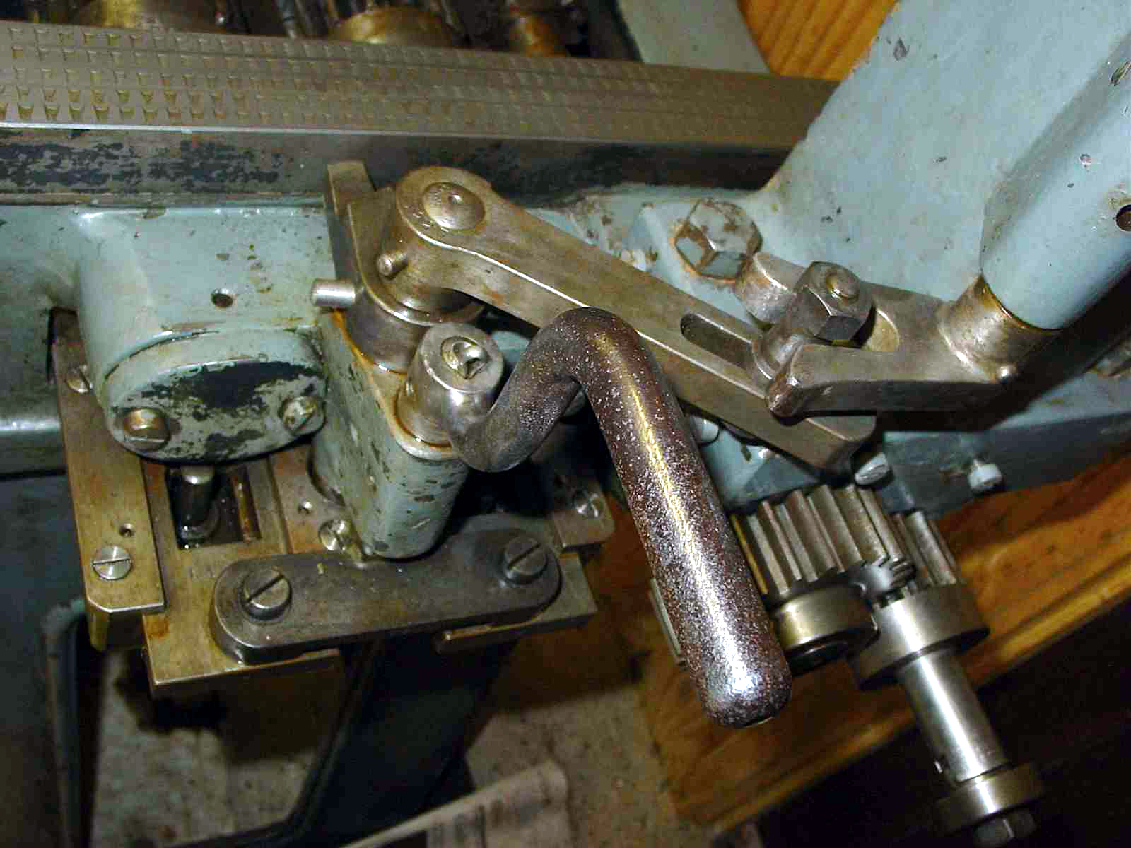
Above: table drive in neutral
Adjustable stops running in a T slot along the edge of the table engaged with a tumbler mechanism that was tripped by stops fastened to the edge of the table; a handle was provided to give manual override and independent operation where a job was nearing a critical phase. The cutter head was indexed along the beam by a ratchet driven by, and interconnected with, the table feed controls.
|
|
|
|
|
 |
|
|
|
|
|
|
|
 |
|
|
|
|
|
|
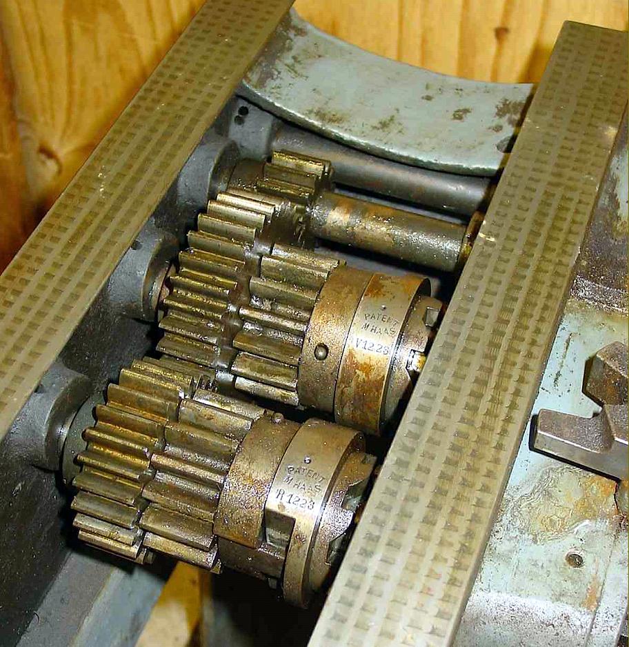
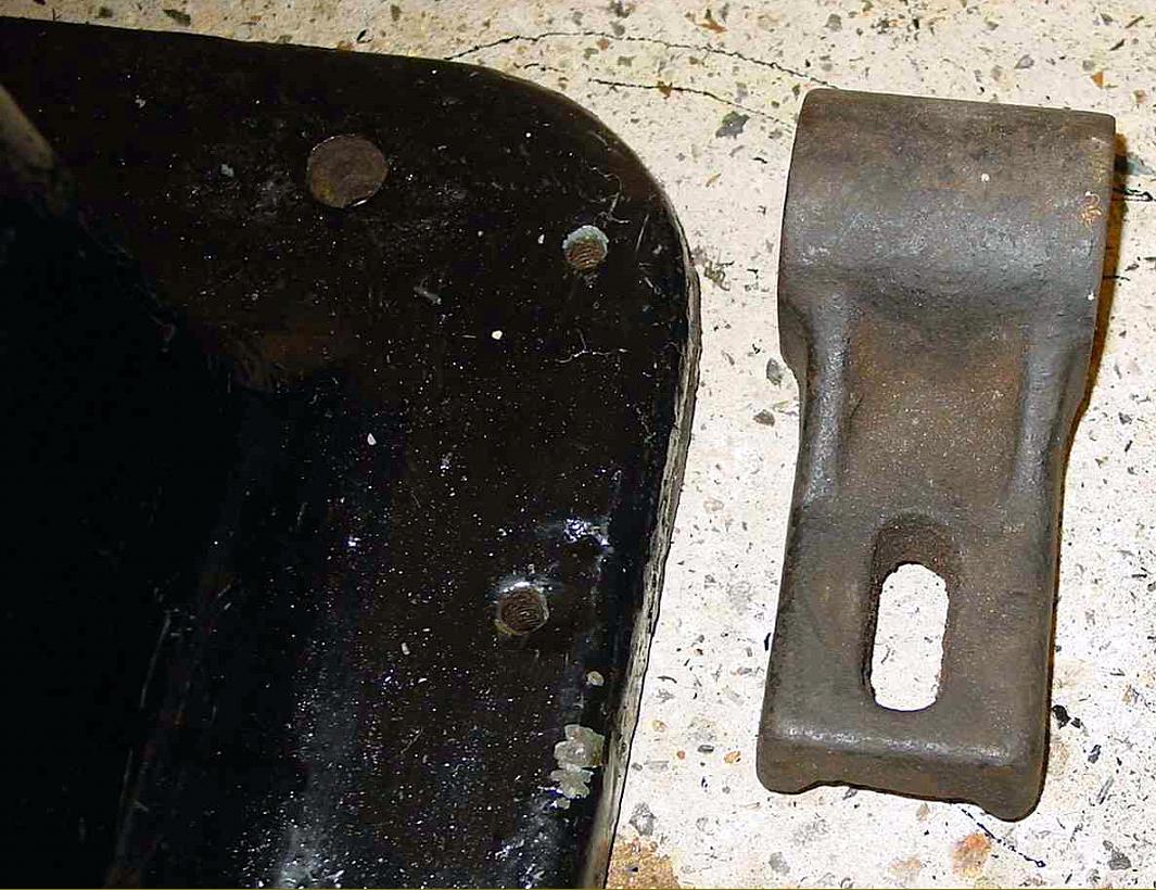
Two parallel shafts and dog clutches provided the table reverse mechanism - and this was arranged to provide a gradual, shock-free take up.. Note, on the nearer ratchet, just below the Hass "Eureka" patent stampings, a large cut-out, Into this is fitted an enormously powerful, C-shaped spring - pinned into position at one end - that slowed down the engagement motion.
|
|
|
|
|
|
|
 |
|
|
|
|
|
|
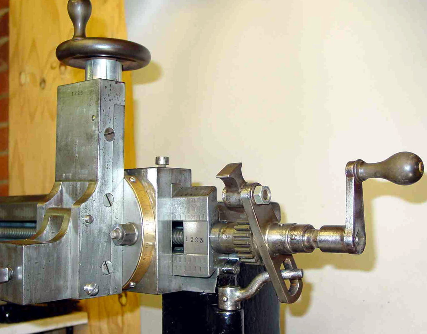
Power feed to the cutter head on some versions was in one direction only (with return was by hand) but others had power available in both directions
|
|
|
|
|
|
|
 |
|
|
|
|
|
|
|
|
|
 |
|
|
|
|
|
|
View beneath of the rocking bar with the rive dog engaged
|
|
|
|
|
|
|
 |
|
|
|
|
|
|
The stamping near the centre of the pulley wheel indicates a maximum speed of 100 rpm.
|
|
|
|
|
|
|
 |
|
|
|
|
|
|
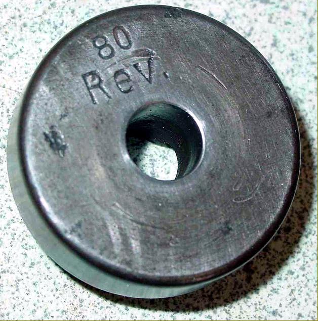
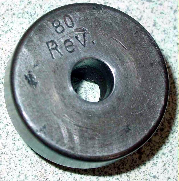
Another example--this time stamped 80 for 80 revolutions
|
|
|
|
|
|
|
 |
|
|
|
|
|
|
Flywheel drive. Amazingly, the shaper was fitted for hand, belt and (almost certainly) treadle operation of the flywheel. The possibility of the latter system being used (though admittedly not fitted to any machine yet discovered) is evidenced by a pair of tapped holes in the base and corresponding fitting points that all align perfectly for that sort of mechanism
|
|
|
|
|
|
|
 |
|
|
|
|
|
|
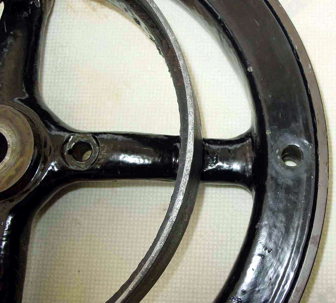
Tapped holes in the base to accept a treadle assembly?
|
|
|
|
|
|
|
 |
|
|
|
|
 |
|
|
|
|
|
 |
|
|
|
|
|
|
|