Jason Lathe
Perris "Pixi", Sartglen "Pixi" & Randa
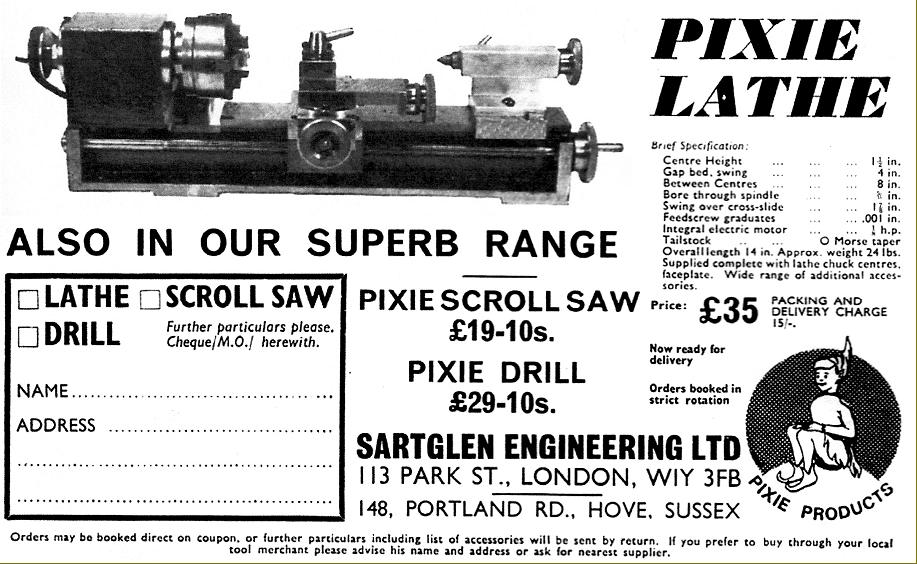
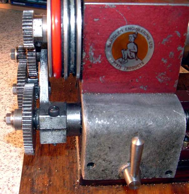
Announced during the 1969 Model Engineering Exhibition, the Pixi lathe was designed and manufactured by Brian Perris, and marketed through Sartglen Engineering Ltd. (part of the Wexler group, a garage and property company) of 113 Park Street, London W1Y 3FB and 148 Portland Road, Hove, Sussex. With a tiny 1.5-inch centre height and a skimpy specification, it did not immediately catch on and, for a while, disappeared from view. The lathe, considerably worked over and with the centre height increased to am more useful 2", appeared next for a short time during the early 1970s when it was being made (or marketed) by L. C. Jay and Son of 19 Oak Street, Norwich and sold badged as the Jason, Perris Pixi and (inevitably) "The New Randa" - the latter marketed by the makers of the original Randa lathe, Ross & Alexander of 165-167 Bishopgate, London E.C.2.
Production - almost certainly by an outside machine shop, possibly Perris - would have re-started during 1971 with the first advertisement appearing in the "Model Engineer" magazine for April 21st, 1972. The Jason was intended to be sold as either a finished product, ready to run, or as set of part-machined casting for the keen model and experimental engineer to finish at home. Rather like the Perris (and its later cousin the present-day Cowells) the Jason was screwcutting - but, unfortunately, without the backgear assembly necessary to reduced the spindle speed to a level where the process could be easily accomplished by a beginner. To get the speed lower, the makers suggested fitting a thyristor speed controller to the motor, or using the special hand-operated threading attachment - similar to that introduced during the early 1970s by Sherline for their miniature lathes and a method employed since the dawn of the screwcutting lathe.
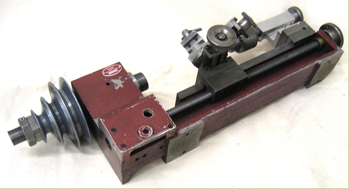
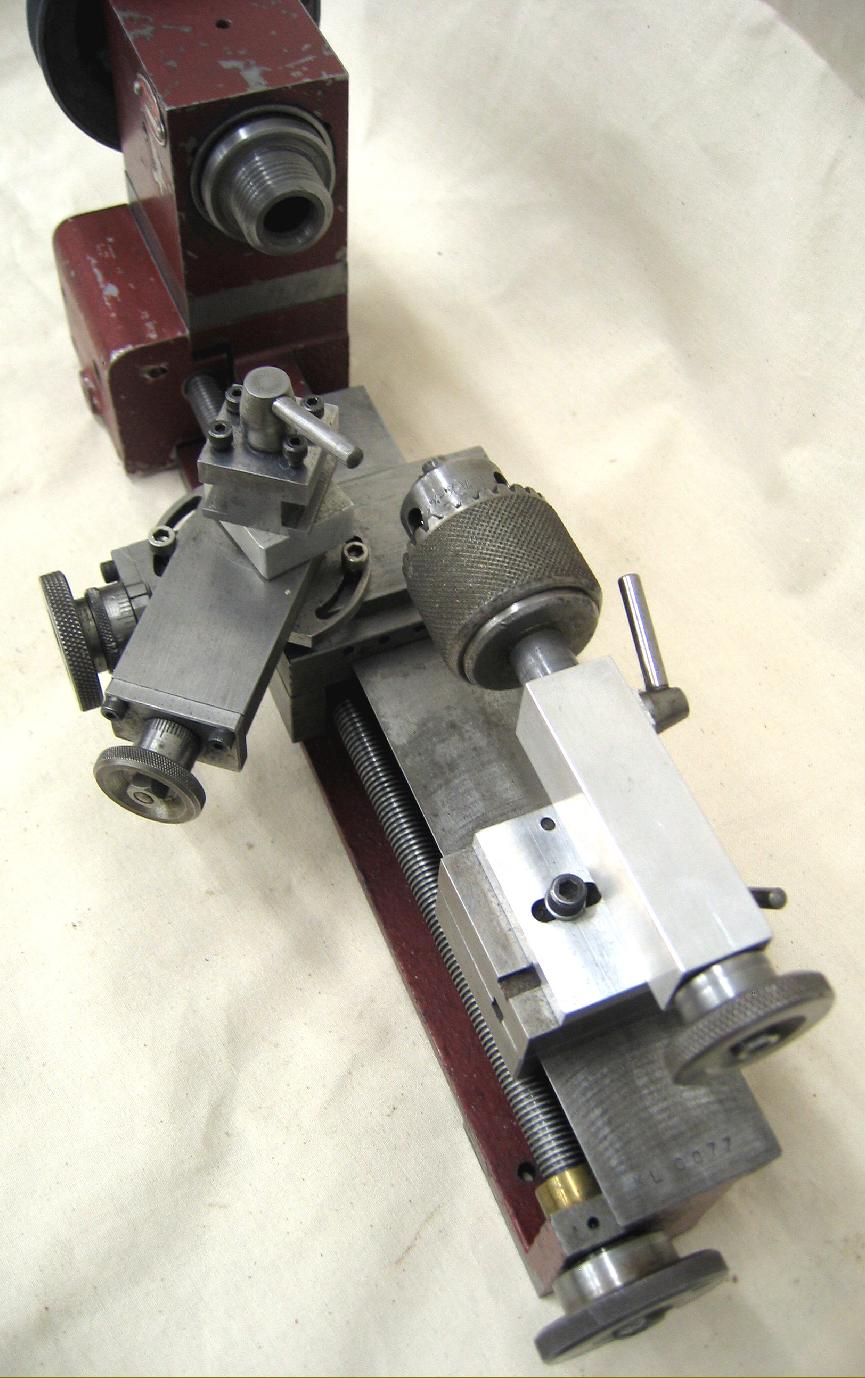
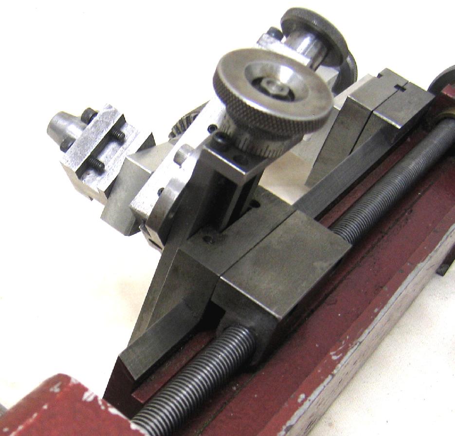
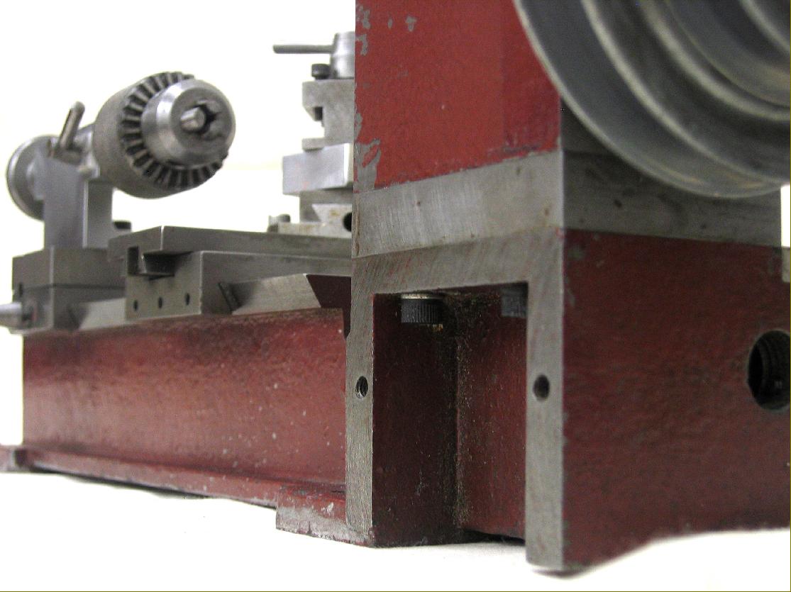
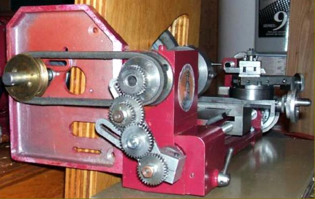
Drive to the carriage was by a full-nut and (with no quick-travel rack drive) all movement of the carriage up and down the bed was by twirling a handle on the leadscrew end. In order to break the drive between spindle and carriage a neat dog-clutch assembly was fitted, in an enclosed box, immediately below the headstock; this simple type of set-up has been shown, over decades of use on many lathes, to be an excellent fitting that allows machining up to shoulders with safety and precision; it is also very easy, as demonstrated by its standard fitting on the Cowells, for an owner to rig up an adjustable automatic trip.
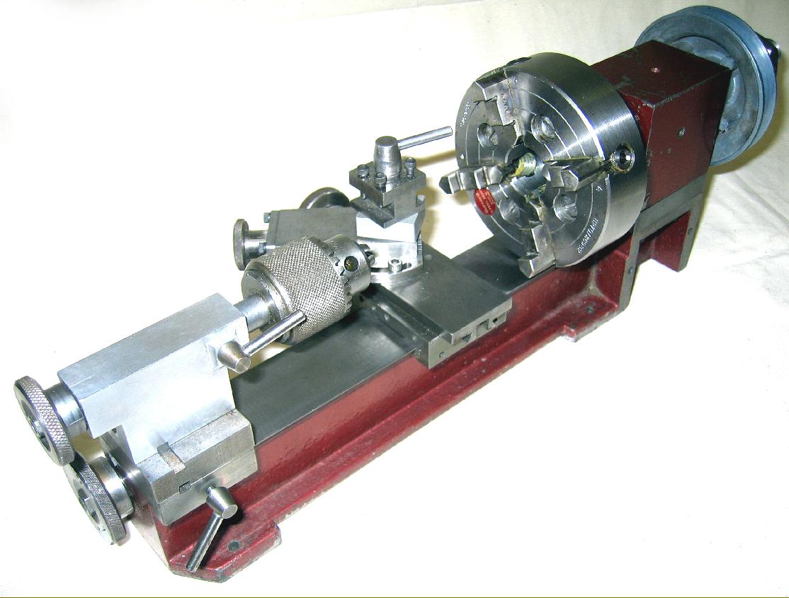
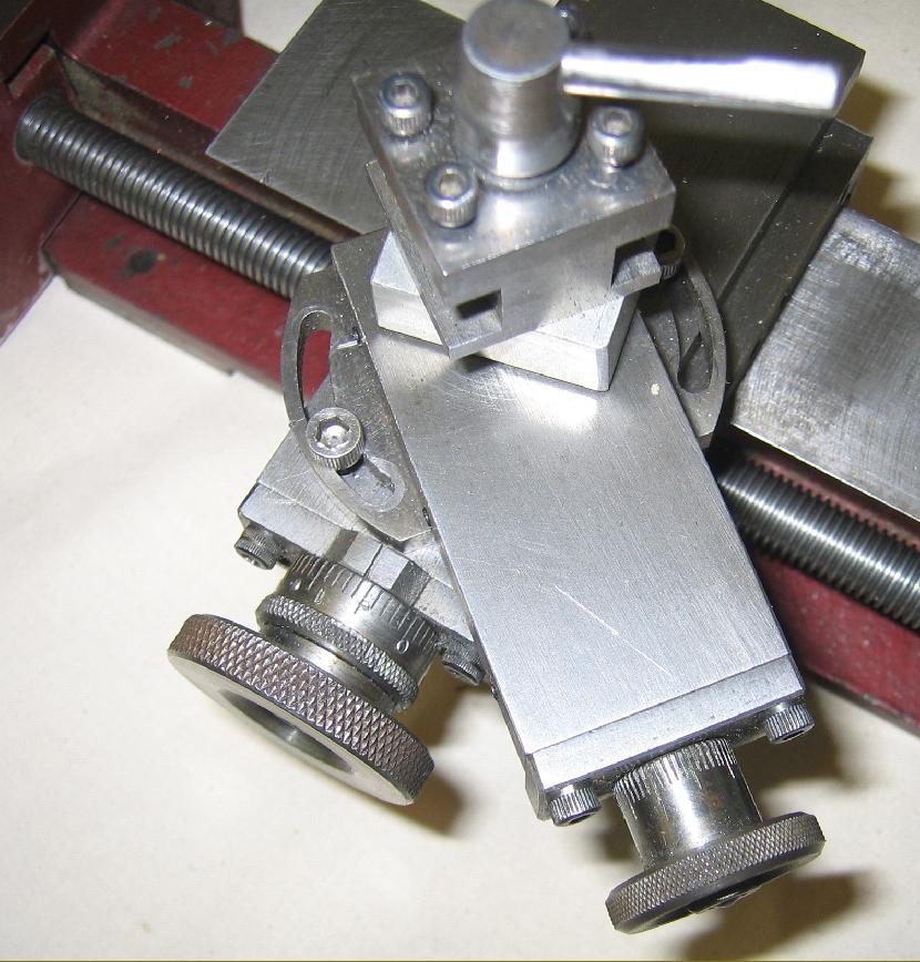
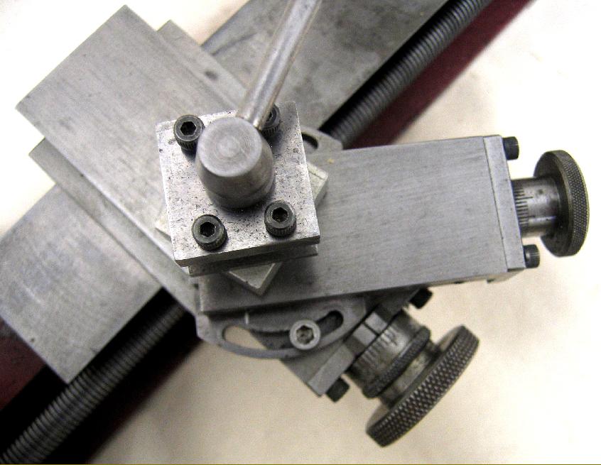
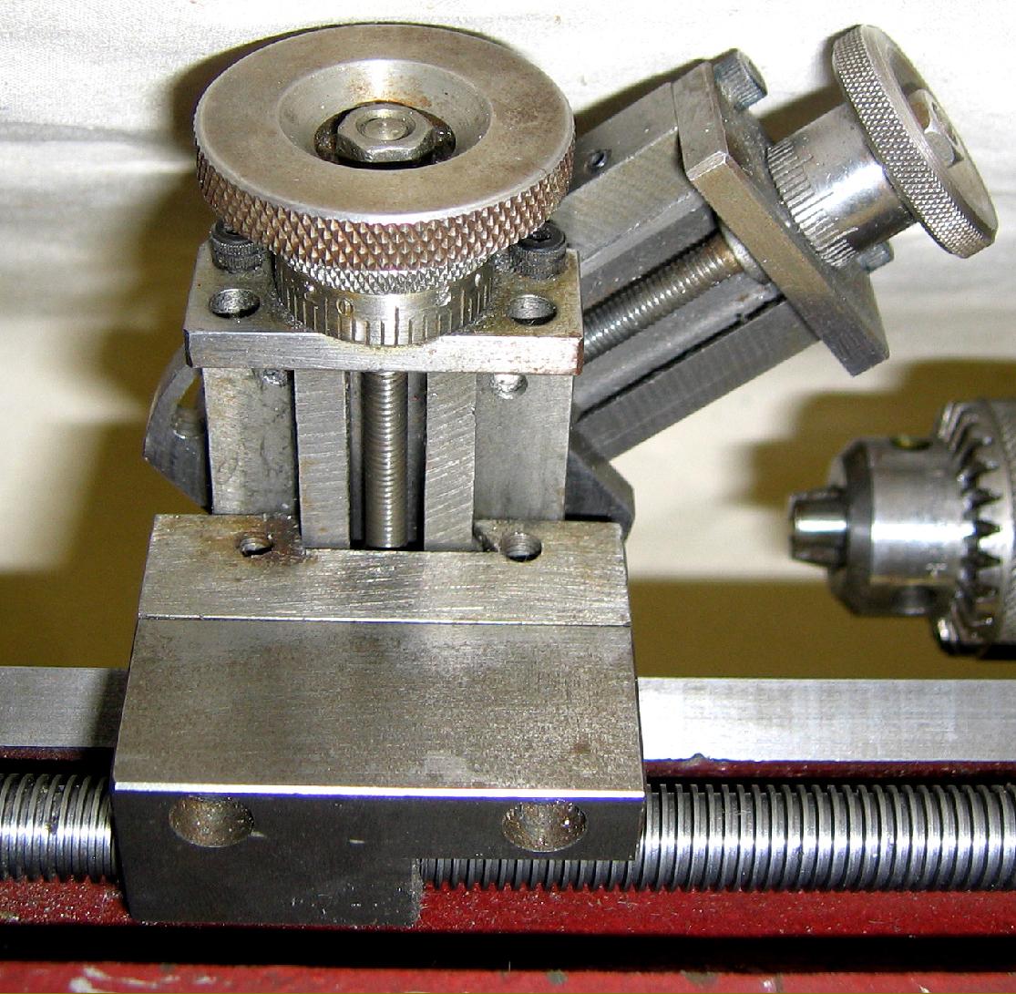
A proper compound slide rest was fitted, together with graduated micrometer dials on both the top and cross slides. However, unlike most small English-made lathes the standard cross was not T slotted but left plain - though an extra-long T-slotted slide was available as an accessory.
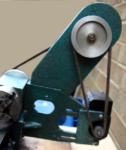
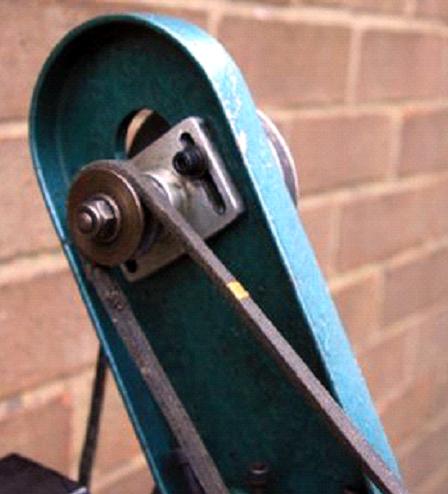
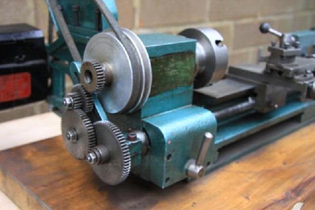
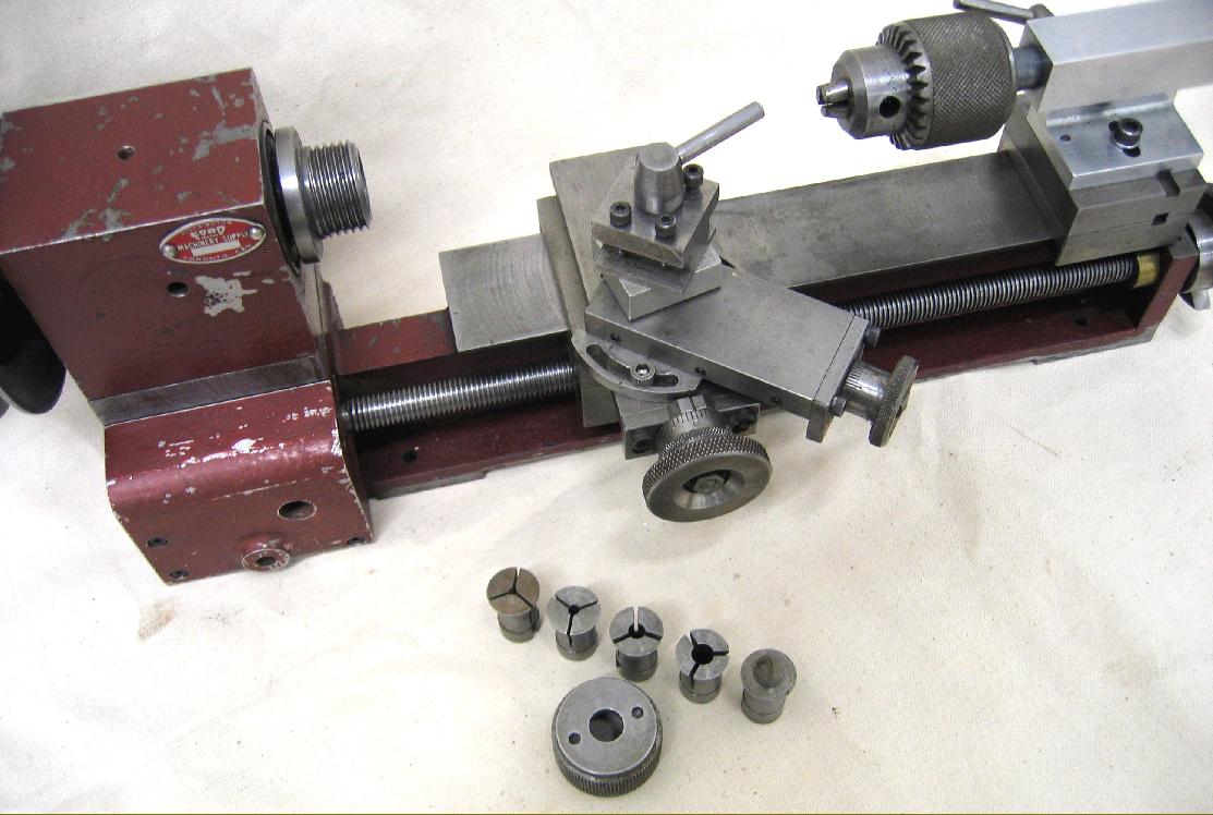
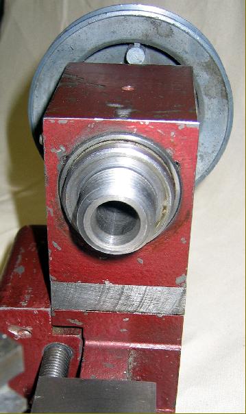
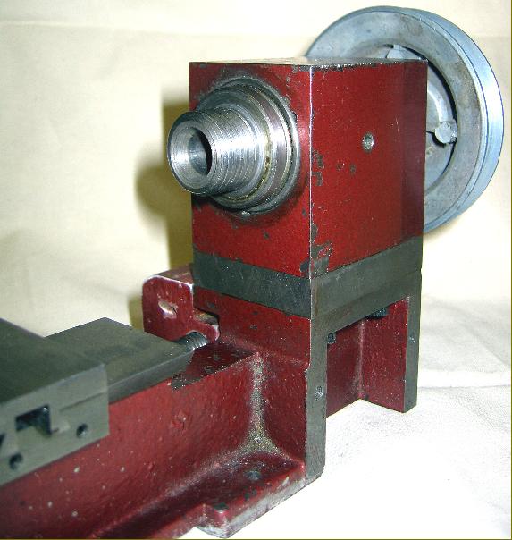
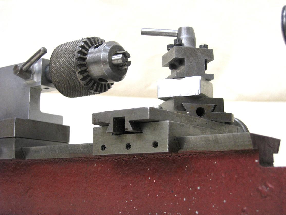
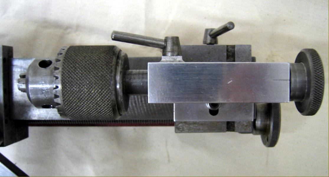
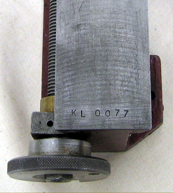
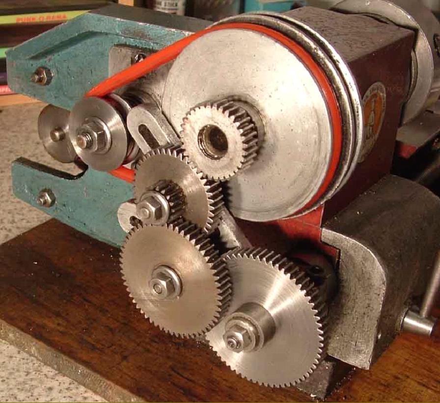
Running in grease-packed, angular-contact ball races - adjustable for preload - the very early headstock spindle had a simple No. 1 Morse taper, but this was quickly changed to a special fitting intended to accept a compression collet with the centre carried (in the usual way) on a solid collet. The motor drove via a two-step pulley to a countershaft fastened to the back of the lathe - then via another two-step pulley to an overhung pulley on the end of the spindle - giving a total of four speeds. Unusually, and in contrast to the long-established, very successful and mass-produced Emco Unimat SL1000 with its round rubber drive bands, all belts on the Jason were in fabric and ran around flat pulleys. However, some examples badged as "Randa" have been discovered with a two-step miniature V-belt pulley on the headstock - and this system nay also have been used on production versions of the Jason.
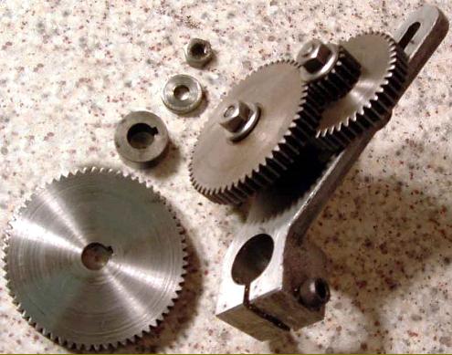
A range of useful accessories was offered including 3 and 4-jaw chucks, a 1/2" raiser block to lift the headstock, an indexing attachment complete with a replica of the lathe's spindle nose, a 3-point fixed steady, T-slotted cross slide, precision machine vice and extra changewheels. On the
Very well built, the Jason showed enormous promise - there were no plastic or "monkey-metal" parts (though one tailstock has been found cast in aluminium) - and nothing appears to have been done to short-cut an honest engineering job. Unfortunately, final development of the machine and its marketing do not appear to have been pursued vigorously enough and, like so many other small-lathe makers before them (and faced with the additional handicap of low-priced competition from the Far East) L.C. Jay and Son abandoned the project..