|
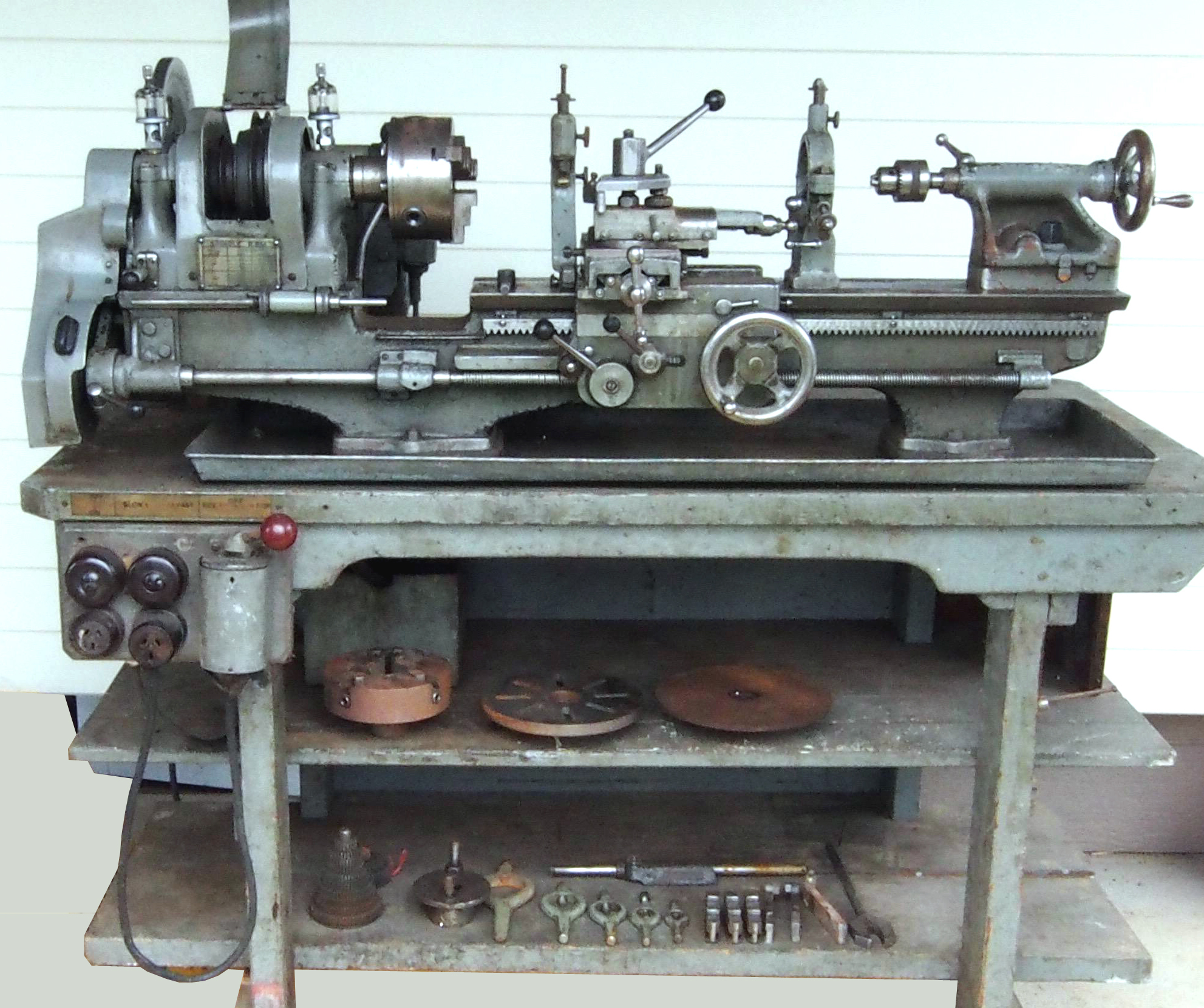
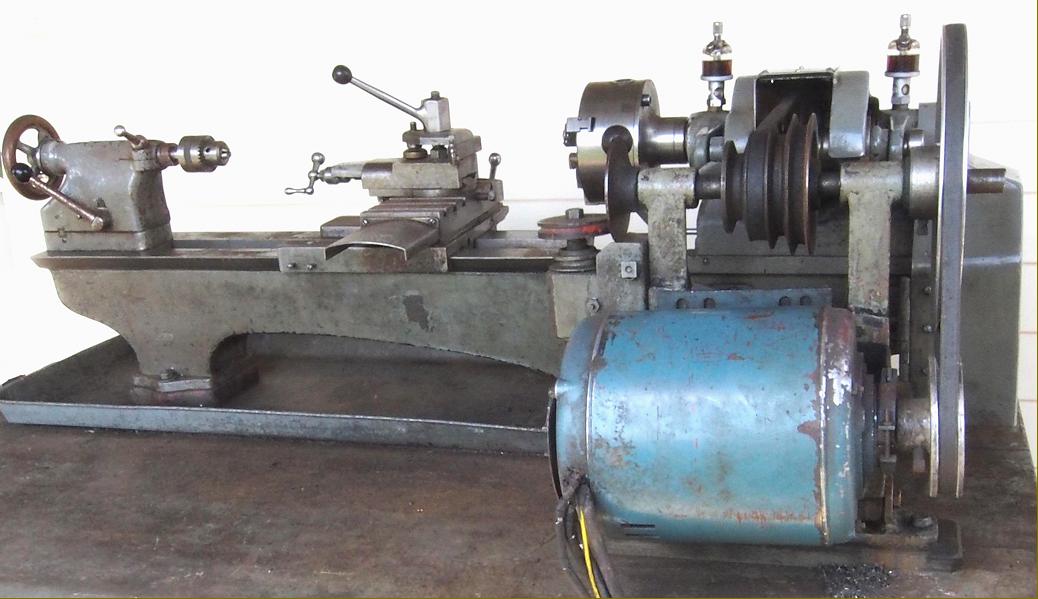
Home-made in Australia by a gifted engineer, Frank Parr, this 4.5" x 24" backgeared and screwcutting lathe was constructed to facilitate the building of a model Ruston Hornsby 11GG horizontal gas engine. Not only was the lathe home-built but so were all the wooden patterns, including those for faceplates and chuck backplates, the parts being cast in a local foundry
A well-thought-out design, the lathe also exhibited a fine build quality and remarkable attention to detail. Based on the popular style used by many English makers of small lathes, the flat-topped, 60° V-edged bed had a gap that was carefully proportioned to give the maximum possible capacity yet minimise, as far as possible, the need for a 3-jaw chuck be to overhung on the spindle nose.
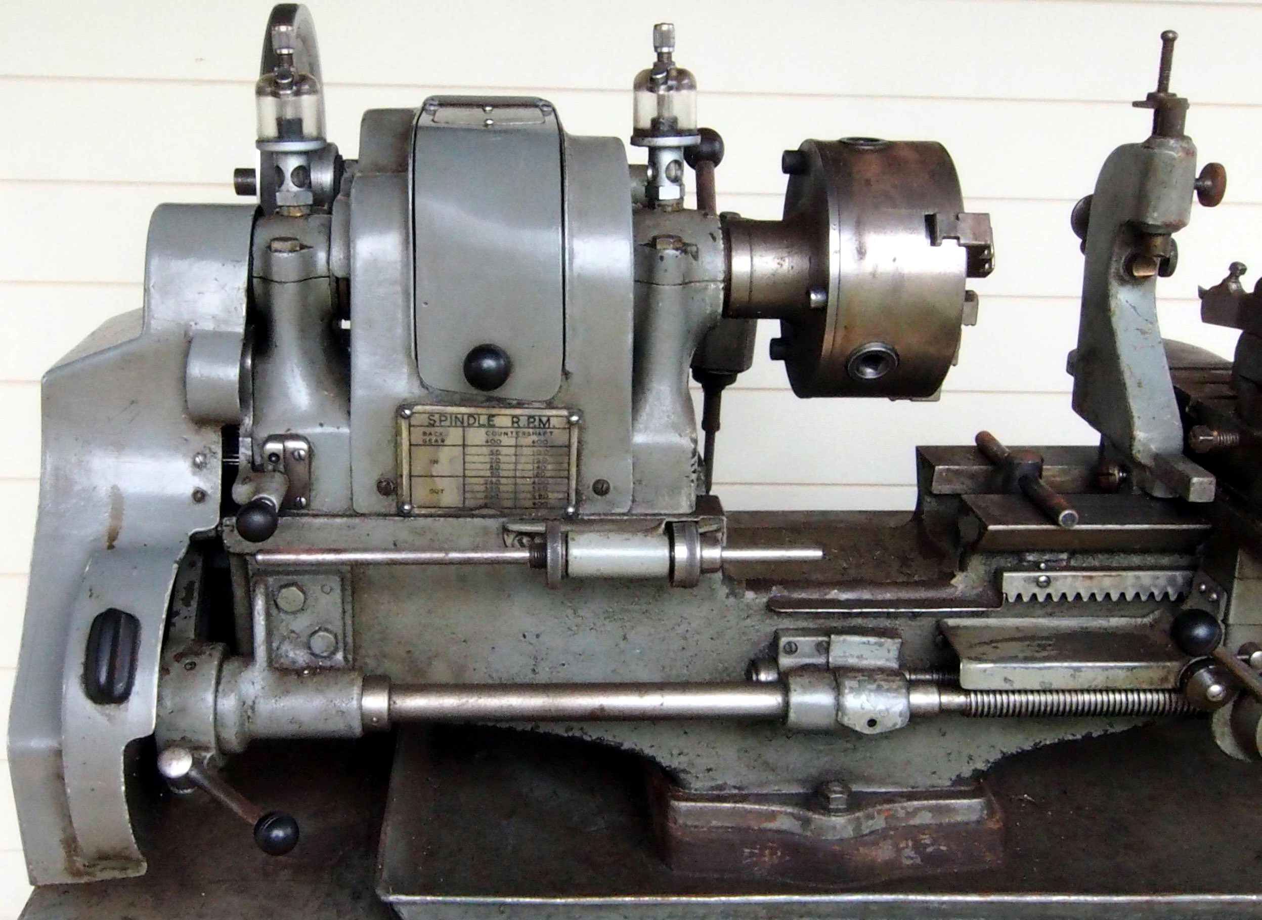
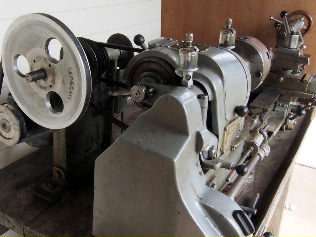
Fitted with plain bearings (secured by 2-bolts caps and lubricated by drip-feed oilers), the headstock was of conventional layout with a rear-mounted 4 : 1 ratio backgear assembly held on an eccentric engagement shaft and the spindle fitted with a 4-step pulley to take an A-section V-belt. Drive came from neat, cast-iron countershaft unit, the belt tensioned by a lever working against a cam. A 2-speed (split-phase) motor was used, running at 1440 and 960 r.p.m. that gave, in conjunction with backgear, twelve spindle speeds of: 50, 70, 80, 90, 100, 120, 140, 180, 260, 350, 400, 460, 520, 600, 680 and 900 r.p.m. Remarkably, for a home-produced machine, all moving parts - backgears, changewheels and belt run - were guarded by neat, closely-fitting cast-aluminium covers.
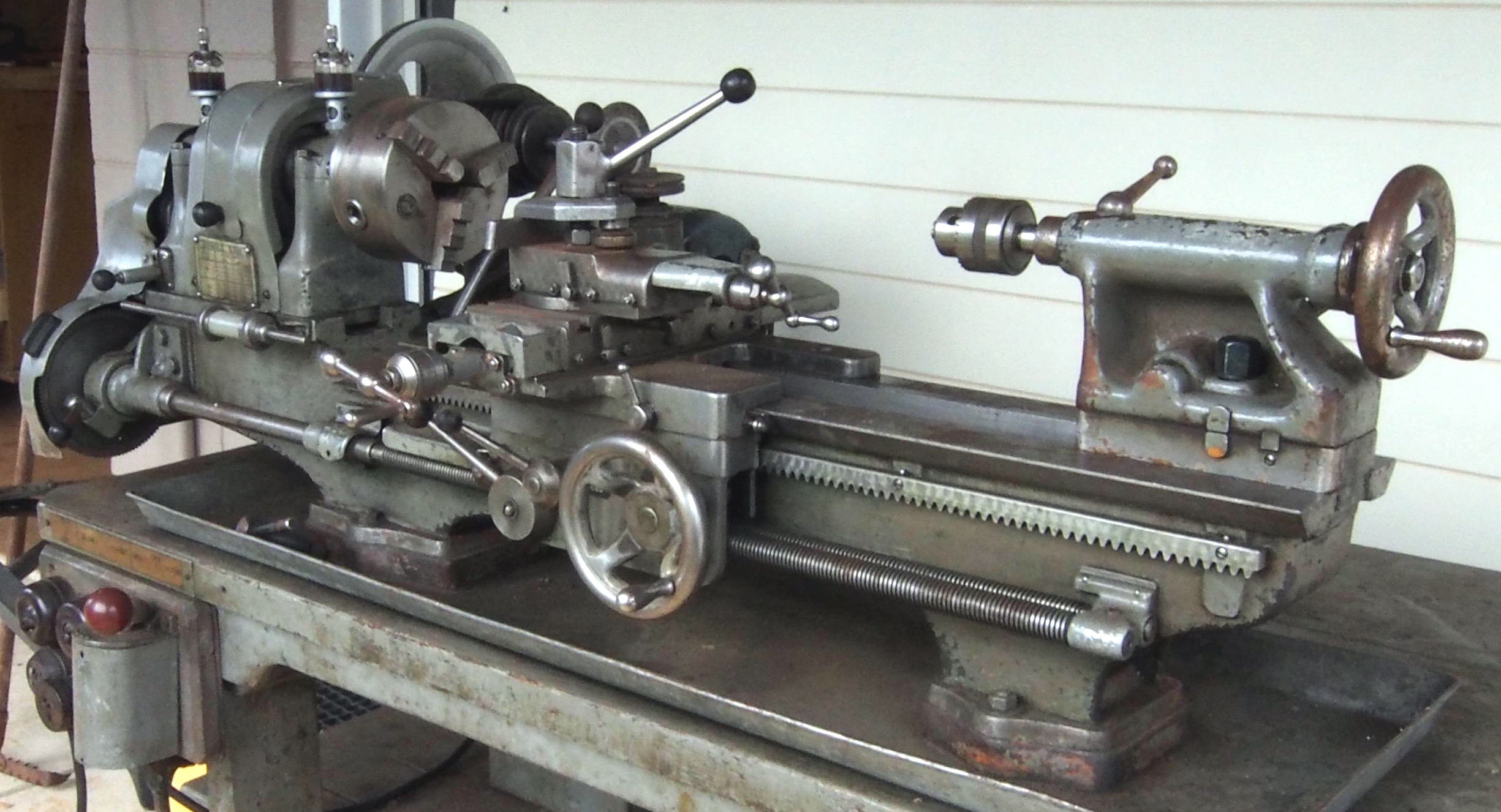
Screwcutting was by a train of changewheels, the drive passing through a tumble-reverse mechanism to the twin leadscrews. Gears were held on a forked bracket clamped in place by a lever that allowed quick and easy repositioning when the ratio needed changing. The reason for employing two leadscrews is uncertain, though as the two were geared together and so ran in opposite directions, it was possible when wanting to reverse the direction of a cut (instead of having to stop the lathe and operate the tumble-reverse lever) to keep everything running and simply engage the appropriate clasp-nut lever on the apron.
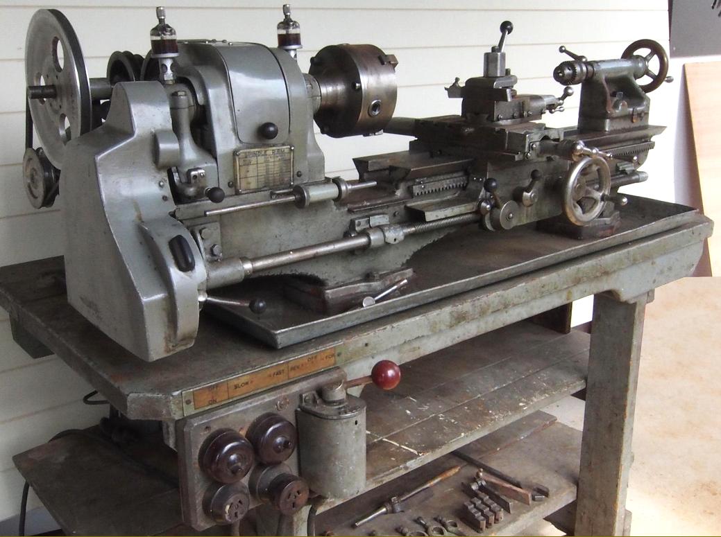
Of ordinary design the compound slide-rest assembly had a T-slotted cross slide with the outer end of its feed screw carried in a Boxford-like bolt-on extension tube - the design enabling the slide to pass over it and so extend the travel when milling. Able to be rotated through 360°, the top slide was retained by pusher screws acting against an inverted cone - as used for decades on the South Bend 9-inch lathe. Gib strips on the cross and top slides were of the conventional push-screw-adjusted type but the saddle was adjusted to the bed by a tapered type - not the easiest of things to machine and get "just right". Each slide was provided with a handy lever-operated lock, the stems being serrated along their length to aid grip with oily fingers. Fastened to the face of the headstock was a long-stem, micrometer-adjusted carriage stop; however, though a neat installation, its location meant that (unlike a bed-clamped unit), it was only useful when working relatively close to the chuck and could not be repositioned to help with work being machined at the tailstock end of the bed.
When the lathe is in the hands of its new owner, the writer hopes to add additional technical details. Some pictures are high resolution and may take time to load
|
|