New Leadscrew and Bronze Bushes
Just like the rest of K81121, the leadscrew had seen better days. Lathes like the ML7 without a seperate power feed shaft for traversing the carriage along the bed do tend to give the leadscrew a harder life, and just like the bed they tend to wear in the area most used, up near the chuck and about 8"-12" back down the bed. Not only does the leadscrew thread wear, but the ends running in the plain bearings (Oilite) suffer just as much, as do the Oilite bushes themselves.
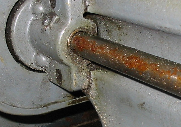
In the picture below you can see just how much wear has occured on the tailstock bearing end. This measured up at around 0.008" undersize, and the oilite bush that this ran in was even worse, at some 0.011" undersize, so you can imagine the slop.

So the next task was a new leadscrew. Myford as usual want an arm and a leg together with a mortgage on your firstborn for parts. These leadscrews are made of EN8, a 0.4% carbon steel, but are not hardened in any form. The EN8 is reasonably tough, often being the first choice for an 'engineering' steel, and unlike mild steel EN8 won't scratch and mark if you so much as look at it. Luckily there are several providers of replacement leadscrew stock in the UK, Kingston Engineering and Halifax Rack & Screw to name but two. Kingston Engineering keep the 5/8", 8 T.P.I., Left-Hand Acme Thread as a stock item for around a third of the cost of the Myford item, so a length was duly ordered.
As it arrives it is just plain stock and the ends need turning down and screwcutting to finish it off. By now I had rebuilt the ML7 to a point where I could actually turn parts on it, but my existing leadscrew was far too knackered for this task, and the new stock was also too big to turn on the Myford. However providence had seen fit to locate a friend with a bigger lathe (a Kerry Toolroom lathe) about 10 miles away, so after a quick phone call a date was arranged for me to turn up and borrow his machine (thanks Charles). I didn't want to waste his time by stopping every 5 minutes to take a photograph, so no pictures of it being turned down and threaded, but suffice to say it was accomplished in fairly short order.
Here's the basic leadscrew data chart from the Kingston Engineering website.
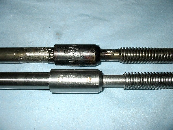
My leadscrew was the 2-piece item rather than the later 1-piece item, and these are generally regarded as a better (read 'safer') option. The 2-piece leadscrews, comprising the main 8 TPI shaft, an intermediate joining bush, and a drive shaft to run in the end bearings, are fixed together in the intermediate bush via a pair of shear pins. If you are unfortunate enough to suffer a crash then the idea is that the shear pins will break and therefore stop spinning the leadscrew and stop driving the carriage any further forward, and minimise possible damage. The later 1-piece leadscrews would just carry on transmitting the power with potentially disastrous results. Myford did change the design of the primary drive gears at a later date, to items made from Tufnol which were designed so the teeth would break off as a safety measure to stop the drive, but many people are still using steel gears here, so the 2-piece leadscrew is preferred.
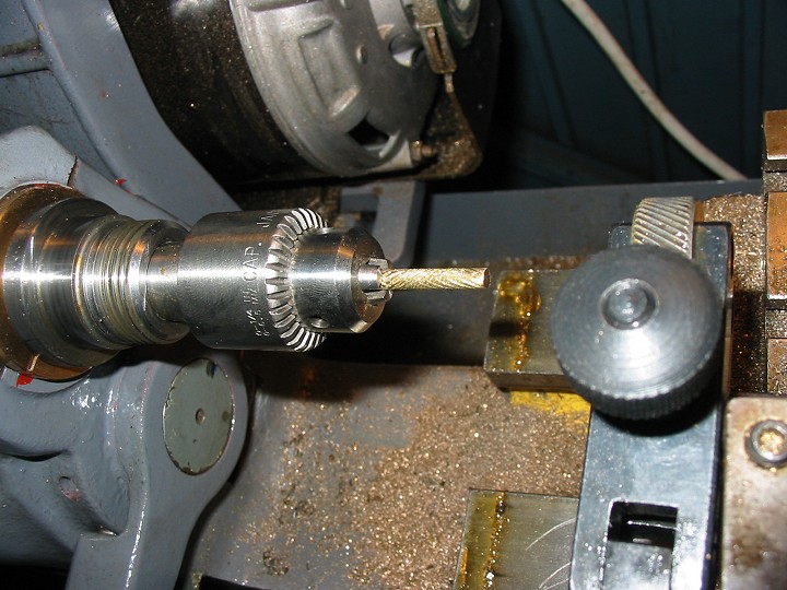
I'd intended to use the original joiner with my new leadscrew, but try as I might I couldn't get if off the old one, so I used the ML7 to turn a new one up. I also made up a new drive shaft from 5/8" Silver Steel, a harder material than the EN8 Myford used, and made up new shear pins from some 3mm dia soft brass. These were turned slightly undersize then knurled to give a light press fit through the joiner and shafts.
I actually used a small MT2 Jacobs drill chuck in the headstock to turn these, as it was easier to get the knurling tool over them this way. Very handy for turning small parts.
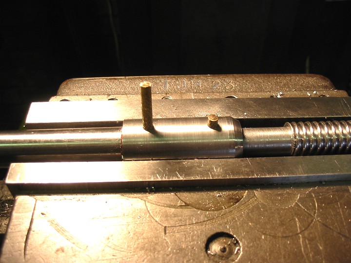
And here is a picture of the old and new drive shafts that connect the gear train to the leadscrew. You can see the wear in the old shaft on the top, and also the new woodruff key seats to drive the gears that I had to cut into the new shaft. Silver Steel is a great material to use for this as not only is it reasonably hard, but it is also precision ground to size with a smooth surface finish for running it in Bronze bearings.
With the leadscrew finished it was now time to sort out the plain bearings it runs in.
This is a close-up of the drive shaft and the Oilite bush taken on the day the lathe arrived. If you look closely you can see the large gap between the bush and the top surface of the shaft where both items have worn badly.
I phoned Myford and ordered 2 new sets of Oilites, one set (2 bushes) for the end shown above, and another bush for the tailstock end. When these arrived I measured them up and found that the ID was undersize by around 2mm/0.080". I called Myford back and explained the problem, but they swore the bushes were the correct items for the ML7, and were the only ones they stocked. They were clearly never going to fit the shafts in a month of Sundays, and the suggested option of boring/reaming them out was not really an option at all, as Oilite bushes can 'smear' when machined and block the pores that release the oil, negating the very reason to use them. So I decided to make some new ones out of Bronze.
A word of caution here for those thinking of doing something similar. Be careful with the grade of bronze you choose. A popular choice for plain bearings is Phosphor Bronze, however this is actually quite a hard material, and if you use it with an unhardened steel shaft you will start wearing the shaft in short order. Phosphor Bronze really needs to be used in conjunction with a hard shaft to avoid problems.
For making these bushes I chose to use an LB4 grade of Leaded Bronze. This has a high (9%) lead content dispersed within the bronze which provides excellent surface lubrication, and indeed is designed to be used where lubrication is poor and maintenance/lubrication intervals are few and far between. It is also softer than Phosphor Bronze and perfect for use with unhardened steel shafts.
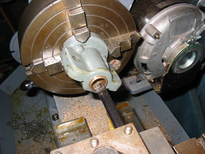
I turned up some blank bushes, with ODs oversize by 0.001" and the IDs undersize by 0.008" and press fitted these into the aluminium bearing housing. This end of the leadscrew bearing housing uses 2 bushes, and these are arranged so that there is a internal gap between the two when fitted, which coincides with the location of the oil nipple so that the shaft can be lubricated. After checking that oil could get in there OK, it was then set up in the 4-jaw chuck and bored to give 0.001" shaft clearance.

The final job was to add a brand new Thread Dial Indicator (TDI) for screwcutting, bought from Myford, and I also fitted a new original Myford Leadscrew Handwheel at the tailstock end, and that was the leadscrew sorted. Time to tackle the next job.