 |
|
|
|
|
|
|
|
|
|
|
|
|
|
|
|
|
|
|
|
|
|
|
|
|
|
|
|
|
|
|
|
|
|
|
|
|
|
|
|
|
|
|
|
|
|
|
|
|
|
|
|
|
|
|
|
|
|
|
|
|
|
|
|
|
|
|
|
|
|
|
|
|
|
|
|
|
|
|
|
From their first appearance in the early 1920s Lodge and Shipley geared-head lathes were subjected to a programme of steady development to improve strength and rigidity and by the 1930s had introduced the Model A lathe. This model was made in three sizes - 12", 14" and 16" - and incorporated all the lessons learned in the previous decades. However, the stated swings were purely nominal - and somewhat understated the machines' true capacities, the real figures being 14.5'', 16.5'' and 18.5'' respectively. Fortunately, even though the lathes were all of identical appearance, one was easily distinguished from another by clear lettering cast into the front of the headstock. Not only were the lathes now much stronger and able to take far heavier cuts, they were far quicker and easier to operate. The strong bed, with its by-now traditional "elliptical girths" between the ways was retained, as was the very successful use of supplementary horizontal and vertical ways inboard of the front V. However, both the apron and screwcutting gearbox were completely revised and the saddle fitted with adjustable front, centre and rear plates that bore against planed surfaces on the undersides of the top ways.
Continued below:
|
|
|
|
|
|
|
|
 |
|
|
|
|
|
|
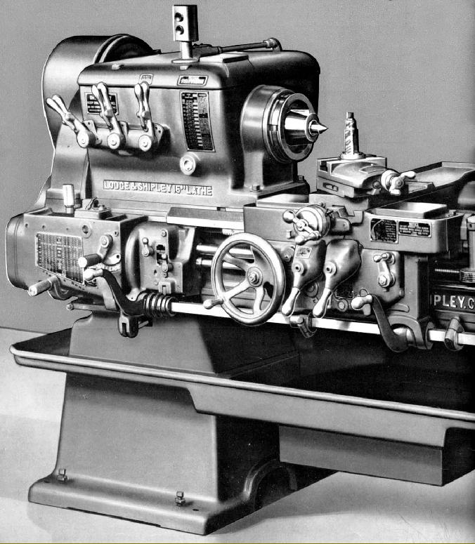
Lodge & Shipley 16-inch Model A - typical of the type
|
|
|
|
|
|
|
|
|
Continued:
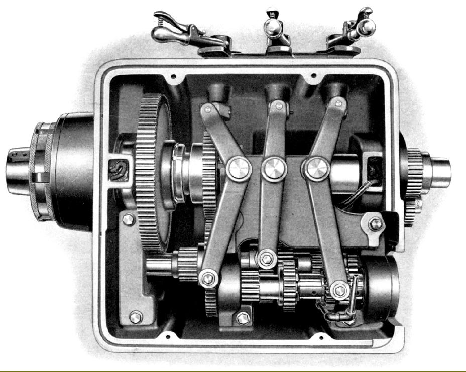
Although the different versions shared a large number of common parts two widths of bed were used, that common to the two larger machines being, at 16 9/16'', some 2 1/2'' wider (but only 1/4'' deeper) than that on the smallest. As standard all models were listed with a capacity of 30 inches between centres but any length could be ordered (subject to a minimum of 18 inches in the case of the two smaller models) in increments of 24 inches. All sizes of the Model A used the same 1.75-inch bore headstock spindle that ran in either plain white-metal bearings or, if specified by the customer, two Timken taper rollers at the front and one ''Norma Hoffman'' cylindrical roller bearing at the rear (interestingly, the makers quoted the radial load rating of the front bearing assembly as 15970 lbs. at 100 rpm.) Oil was distributed by splash and pump, the latter fitted, no doubt, to improve the longevity of the less-expensive white-metal bearings now fitted in place of the original bronze. Felt pads or wicks protected the main bearings from the ingress of dirt and swarf. The headstock was now fitted as standard with a clutch and brake mechanism - operated by a lever pivoting from the right-hand face of the apron (the operator's normal working position) - and, as in earlier years, with the extra-cost option of replacing the brake with a spindle-reverse mechanism. During assembly (in a search for absolute concentricity) after the headstock was bolted to the bed, and its spindle fitted, the latter was finish ground its hardened end - both the external L1 ''long-nose American taper'' and the internal 5-Morse taper bore being treated. The headstock gears were all made from alloy-steel forgings: after hardening the centre splines were ground in and then used as a datum to ensure the gear teeth were finish ground as accurately as possible. The gears ran on ball-bearing supported shafts held in detachable housings secured within the headstock by bolts and sleeves ground to produce the effect of a doweled location. One advantage of this construction was that the layshafts and their gears could, if necessary be removed without disturbing the rest of the headstock assembly. Even thought some earlier models of Lodge & Shipley lathes had used a self-contained drive system with the motor mounted (with little room to spare) inside the headstock-end plinth the later machines used a far more sensible arrangement with the motor easily accessible on an adjustable pivoted plate mounted on the back of the headstock-end bed plinth. Drive from the motor was by multiple V-belts guarded by a swing-open cover. Either a single-speed (1800 rpm) or two-speed (900/1800 rpm) motor could be specified and, in the case of the former, with either a low-speed ( 18 to 540 rpm) or high-speed (36 to 1080 rpm) range. If the 2-speed motor was specified then both ranges were available giving a useful total of 24 speeds. Lathes were supplied with motors matched to the size of lathe: 3 hp for the 12-inch', 5 hp for the 14-inch and 7.5 hp for the 16-inch.
In the original design of headstock, because the plain bearings needed bolt-on caps, the headstock casting was split on a line level with the spindle centre and, even though this meant a head joint only just above the oil level, no provision was made for a sealed or gasketed joint. The makers claimed: ''Oil seeping past the joint is caught in grooves cast in the cover and base and is returned to the reservoir.....'' By the early 1940s, the design of the headstock had been thoroughly modernized with the option of plain bearings dropped and roller bearings fitted as standard. As a consequence, because there was now no longer any need for the casting to be split horizontally along centre line of the spindle (to accommodate the plain-bearing caps) the casting walls were extended upwards to form an open-topped box that stiffened the whole assembly. The headstock cover became just a cap plate, bolted on well above the oil level. Lubrication was by a combination of pump and splash with oil to the bearings filtered through either felt pads or wicks.
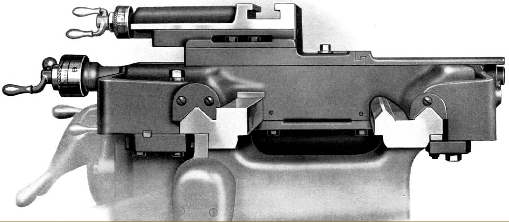
Whilst the basic operating principles of the apron remained unchanged the structure was considerable improved by the use of a very much more rigid double-wall construction. All apron gears were made from heat-treated alloy steel and ran on hardened and ground bronze-bushed shafts supported at both front and rear. As before, power sliding and surfacing feeds were transmitted through independent friction clutches - but now operated by simply lifting or lowering hefty levers (instead of a tedious screwing-in of a slippery wheels) giving the tremendous advantage of being engage and disengage either drive instantly. A cam-operated plunger-type oil pump was also incorporated and, drawing its supply from a reservoir in the base, distributed lubricant not just to all parts of the apron but also the font and rear bed and cross-slide ways and the cross slide. The pump worked when either of the power feeds was in use - and also when the carriage was moved more then a few inches by hand; as a consequence it was recommended that, on shorter manually-traversed jobs, the operator occasionally move the carriage backwards and forwards a foot or so to keep the oil flowing. As a safety precaution small reservoirs were provided, built into the tops of both front and back walls, that were replenished directly from the pump. A sight level glass was included to let the operator know when a top-up was required - with waste-preventing metering valves built into the system to ensure that the supply should last around a week under normal operating conditions. .
Continued below:
|
|
|
|
|
|
|
|
|
|
|
|
|
|
 |
|
|
|
|
|
|
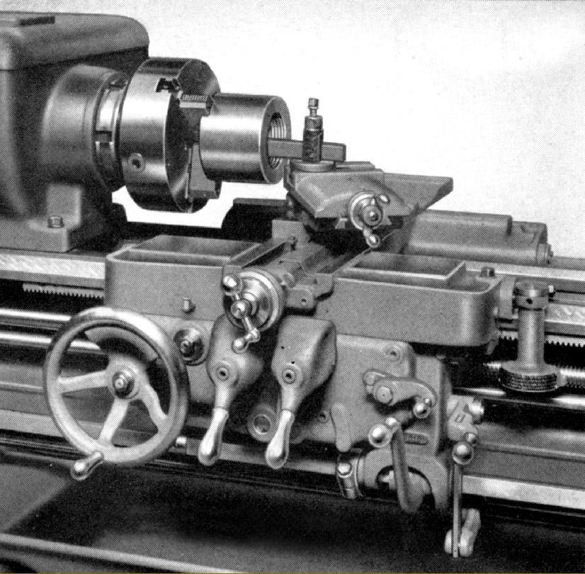
Whilst the power feeds was still transmitted through apron-mounted clutches these were now by simply lifting or lowering hefty levers.
|
|
|
|
|
|
|
|
|
Continued:
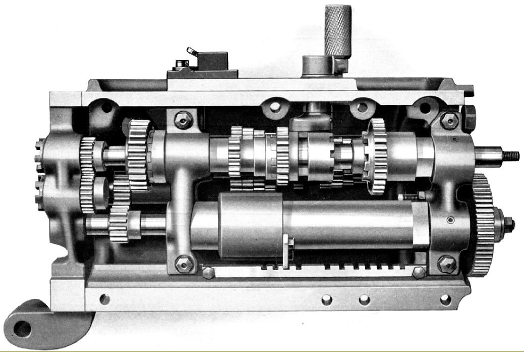
A separate unit, bolted to the front of the bed (the maker's first boxes had been built into the bed casting beneath the headstock), the screwcutting gearbox had no opening at the top to let in dirt or stray turnings. Gears were of heat-treated steel with strong, coarse-pitch teeth and ran on nickel-steel shafts supported in bronze bearings. The same box was fitted across the range and could generate 55 English-pitch (inch) threads from 2 to 128 tpi and 55 rates of sliding feed from 0.0014'' to 0.090'' without dismounting or repositioning any changewheels. Although the ordinary thread range was adequate to cover the great majority of jobs (likely to be encountered in the average machine-shop) a coarse threading attachment was also offered that enabled the generation of pitches eight times coarser than standard. By purchasing extra sets of gears ranges of diametral, module and, of course, metric pitches could also be cut. As an alternative, for use in plants where only products measured in mm were manufactured, lathes could be supplied as all-metric machines with mm-pitch compound-slide feed-screws, leadscrew and screwcutting gearbox.
Both the gearbox and its drive train from the headstock were fitted with a one-shot lubrication system manually operated by a lever on its top cover. Also shared by all models were the 115/16''-diameter, 4 t.p.i leadscrew (made in-house on special leadscrew -cutting lathes ) and the robust 1''-inch square stop-rod used to automatically disengage the sliding feed in either direction.
Continued below:
|
|
|
|
|
|
|
|
 |
|
|
|
|
|
|
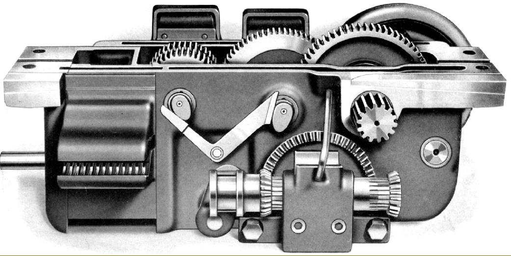
The new apron was considerably stronger with double walls and a lubricant supply held in the base
|
|
|
|
|
|
|
|
|
Continued:
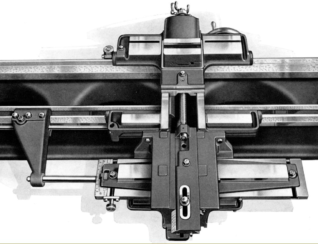
Surprisingly (for so robust a series of lathes) the standard cross slide was not a full-length type but a comparatively short affair with a ''clip-on'' extension section at the rear to shield the feed screw from swarf - and the ability to receive an extension piece for the taper-turning attachment. The cross-slide ways were ''inverted'' into the saddle and extended forwards to allow the slide a decent amount of travel before it came up against the inside face of the micrometer dial. The cross feed screw was of large diameter and, to work easily with the taper-turning attachment, of the telescopic type. The bronze cross-feed nut was of the ''compensating'' type - split and adjustable to take up backlash.
As usual on Lodge and Shipley lathes the cross feed screw incorporated an ingenious mechanism that allowed an adjustable depth stop to be set for both turning and threading. Because the tool could be withdrawn by up to three revolutions of the handwheel, and run in again without the micrometer-dial reading changing, it was possible to accurately measure the depths of successive cuts. The top slide was clamped down by 4 bolts and swiveled through 360°. It was supported on a wide surface that ensured there was a minimum of overhang no matter what its position.
By the end of the 1930s Lodge and Shipley had a line of lathes able to take full advantage of the latest developments in cutting tool technology; even though the company's machines of 20 years earlier had appeared robust and up-to-date, along the tough new models they appeared to be almost hopelessly inadequate. During the 1940s and 1950 further incremental improvements were made to rigidity, metal-removing performance, ease-of-use and reliability - as can be seen in the Model X models of the 1940s and early 1950s and Powerturn lathes of later years..
|
|
|
|
|
|
|
|
 |
|
|
|
|
|
|
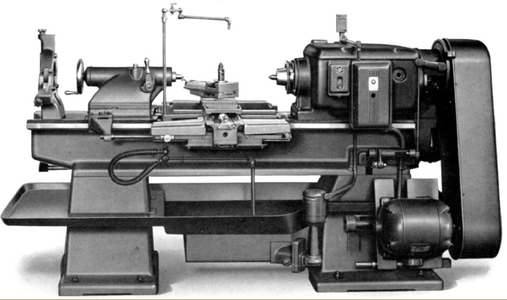
Even thought some earlier models of Lodge & Shipley lathes had used a self-contained drive system with the motor mounted (with little room to spare) inside the headstock-end plinth the later machines used a far more sensible arrangement with the motor easily accessible on an adjustable pivoted plate mounted on the back of the headstock-end bed plinth. Drive from the motor was by multiple V-belts guarded by a swing-open cover.
|
|
|
|
|
|
|
|
 |
|
|
|
|
 |
|
|
|
|
|
 |
|
|
|
|
|
 |
|
|
|
|
|
|
From the early 1920s the Lodge & Shipley bed was modified to include two extra ways that the makers described as "supplementary bearings". The first was created on the horizontal surface (also used by the tailstock) between the inside edge of the front V and the gap between the front and rear Vs; the second was directly in line with tool thrust and formed on the inner vertical surface between the front and back Vees This arrangement meant that the carriage was precisely guided on very long V ways (a process that also tended to even out wear) yet with a substantial proportion of the tool thrust absorbed against a vertical rather than inclined surface. This improved bed-to-saddle arrangement was to become a feature of all Lodge & Shipley lathes until the 1950s and, far from being left alone, was steadily developed until the height of the inner flat eventually rose to equal that of the top of the front V.
|
|
|
|
|
|
|
|
 |
|
|
|
|
|
|
|
|
|
|
|
 |
|
|
|
|
|
|
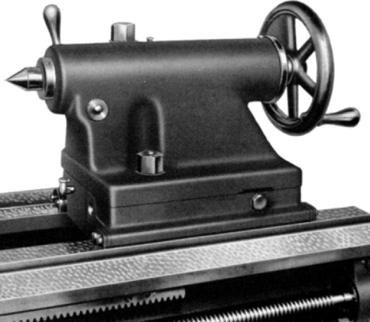
Tailstocks were bored (on superb American-made Heald Borematics) with a single-point tool in a continuous through cut that ensured a perfectly straight and round hole.
|
|
|
|
|
|
|
|
|
|
|
|
|
|
|