|
Home Machine Tool Archive Machine-tools for Sale & Wanted Books Accessories Hendey Home Page Hendey Literature is available |
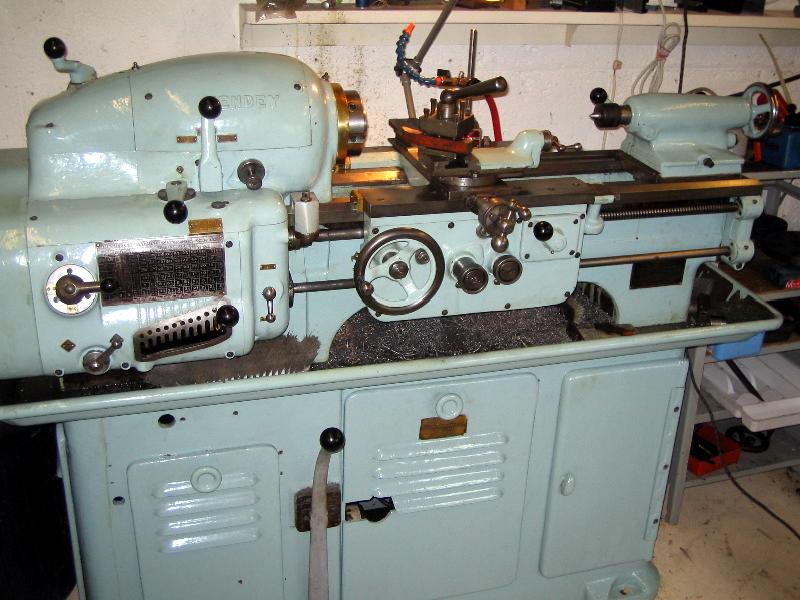
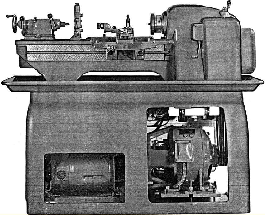
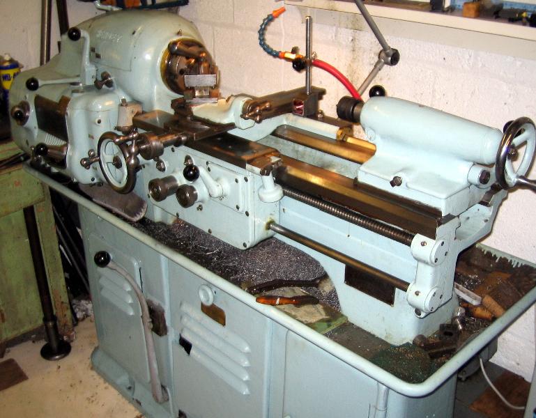
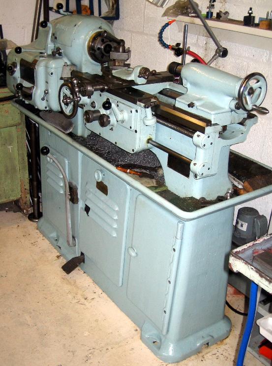
Solidly built (it weighed over 3100 lbs) and beautifully made the Hendey 9" x 24" (or, optionally x 36") high-speed precision Tool and Gage-Makers' lathe has long been a sort-after machine. The headstock gears and shafts were made of heat-treated, alloy steel and the 1.5" bore spindle, also of alloy steel, had a hardened nose marked with graduations to assist in cutting multi-start threads and was finished to precision limits. It run in super-precision bearings at both ends (the front pair being pre-loaded) and was provided with a push-in lock button (to assist with the mounting of chucks, etc) positioned on the front face of the headstock. The pulley that drove the spindle ran on its own bearings, concentric with those of the spindle and, because the spindle had nothing rotating on it between its own bearings, was thus isolated from any interference by belt loads, or vibration, from the base-mounted drive system. The spindle nose carried a standard Cam-Lock Type Dl-4" and the centre was bushed to a Morse No. 5 that could be removed and replaced by a set of 15 spring collets from the Hendey No. 6 Set (from 1/8" to 1" by 16ths). A special oversize collet of 11/8" capacity was also available. The stepless-speed range in direct drive (both forward and reverse) was 500 to 2000 RPM and in backgear (by very low pitchline velocity gears) 40 to 500 RPM. The spindle was started and stopped by means of a multiple-disc clutch, coupled to an automatic brake that was activated by moving the clutch lever into its neutral position. The drive system was similar in its arrangement to that employed on contemporary toolroom lathes of similar quality (the Monarch 10EE for example): a D.C. generator was housed in the cast-iron lathe stand and driven by a standard 3-phase A.C. motor mounted above it. The output from the generator was controlled electronically and passed to a 3 HP DC motor (thus maintaining a high torque at low speeds) that drove the headstock spindle via three V belts.
Continued below:
|
Continued: |
|
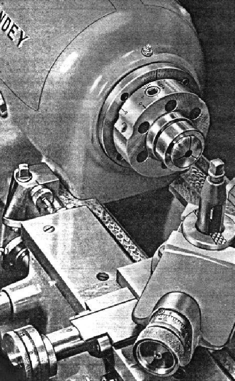
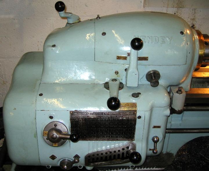
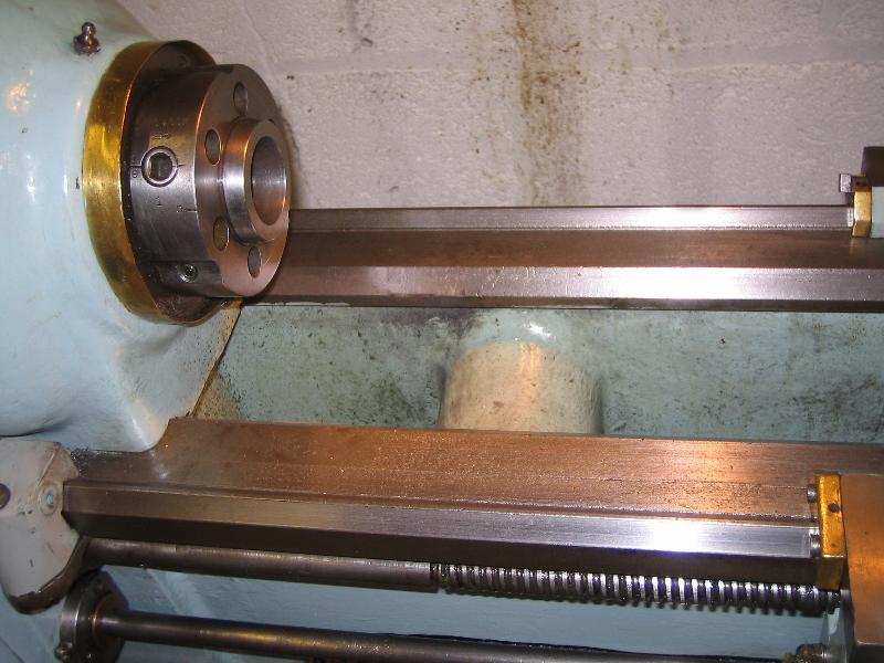
Headstock with collet adapter - and showing the graduations used to assist with machining multi-start threads. |
||
|
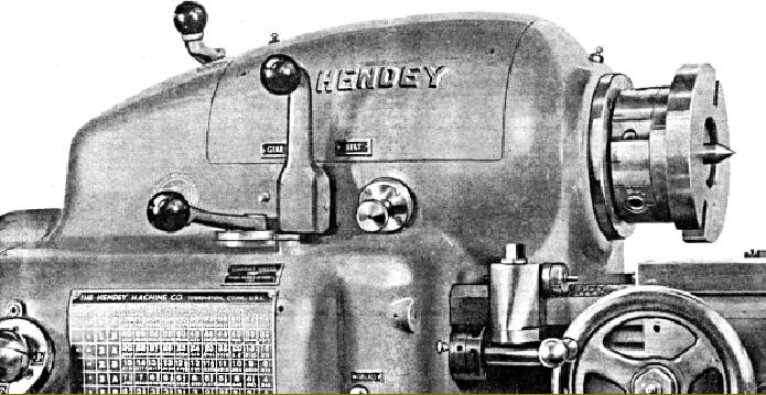
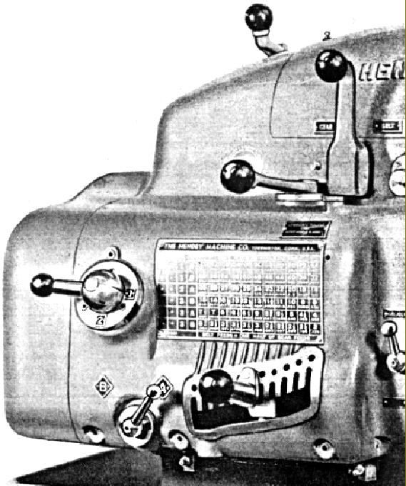
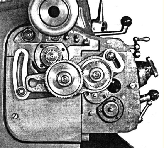
With 66 different threads available, without changing or resetting any gears on the quadrant arm, the quick-change gearbox gave and was also provided, in best tradition of high-quality lathes, with an additional drive by means of a belt that gave feed rates one-half those by gear |
|
|
|
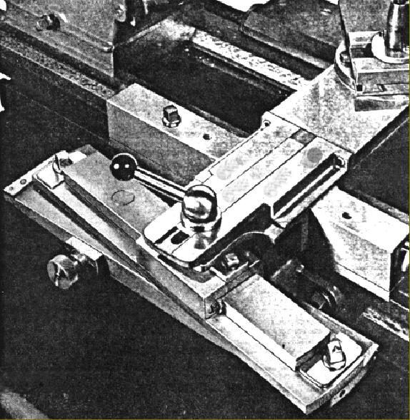
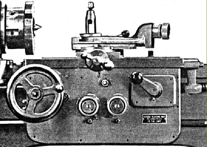
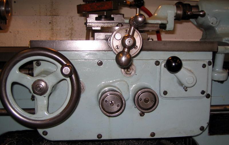
The apron was of the double-walled type with shaft bearings in both walls, including that for the rack-drive pinion; power sliding and power surfacing was fitted, each engaged by a friction clutch operated by its own screw-in knob. |
||
|
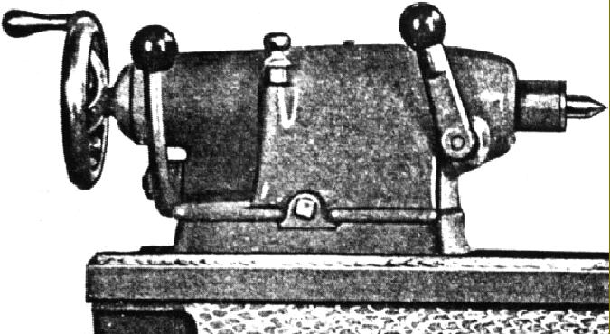
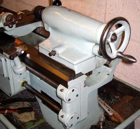
The set-over tailstock was especially sturdy and employed a barrel clamp that drew the spindle to the centre - whilst applying an upward pressure to keep it in alignment with the headstock spindle. The tailstock clamping arrangement was a form of eccentric (subject to patent No. 1,666,484) and the barrel was graduated in 1/32" and engraved with a centre line to assist in the setting of tools. |
||
|
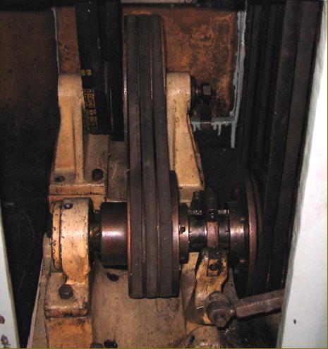
The drive system differed only in detail from that employed on contemporary toolroom lathes of similar quality; a D.C. generator was housed in the cast-iron lathe stand and driven by a standard 3-phase A.C. motor mounted above it. The output from the generator was controlled electronically and passed to a 3 HP DC motor (thus maintaining a high torque at low speeds) that drove the headstock spindle via three V belts. The smaller English Cromwell lathe used a very similar system. |
||
|
Home Machine Tool Archive Machine-tools for Sale & Wanted Books Accessories Hendey Home Page Hendey Literature is available |