|
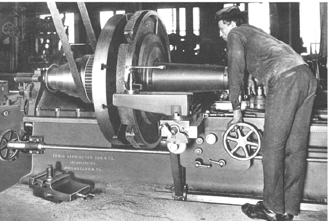
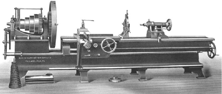
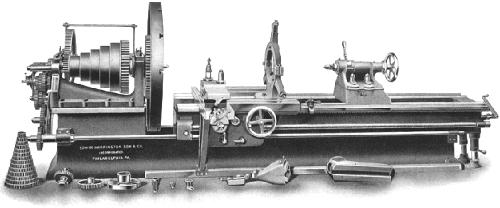
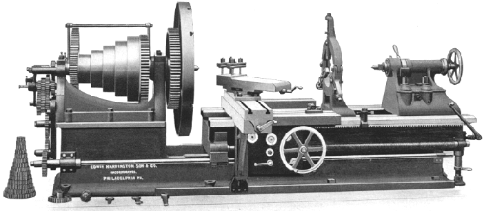
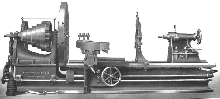
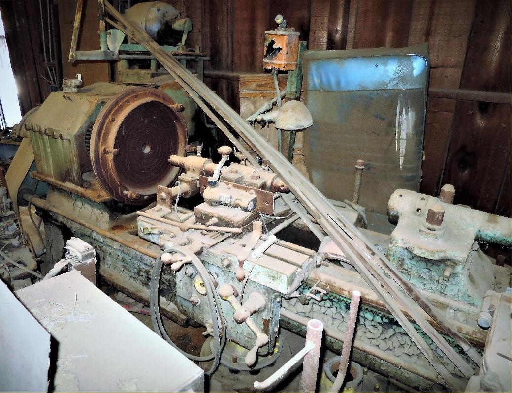
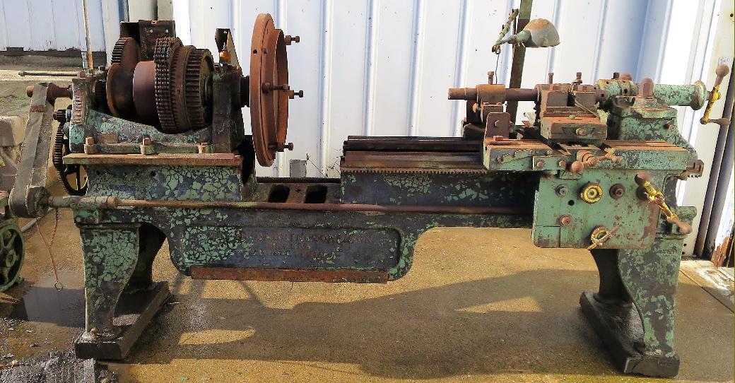
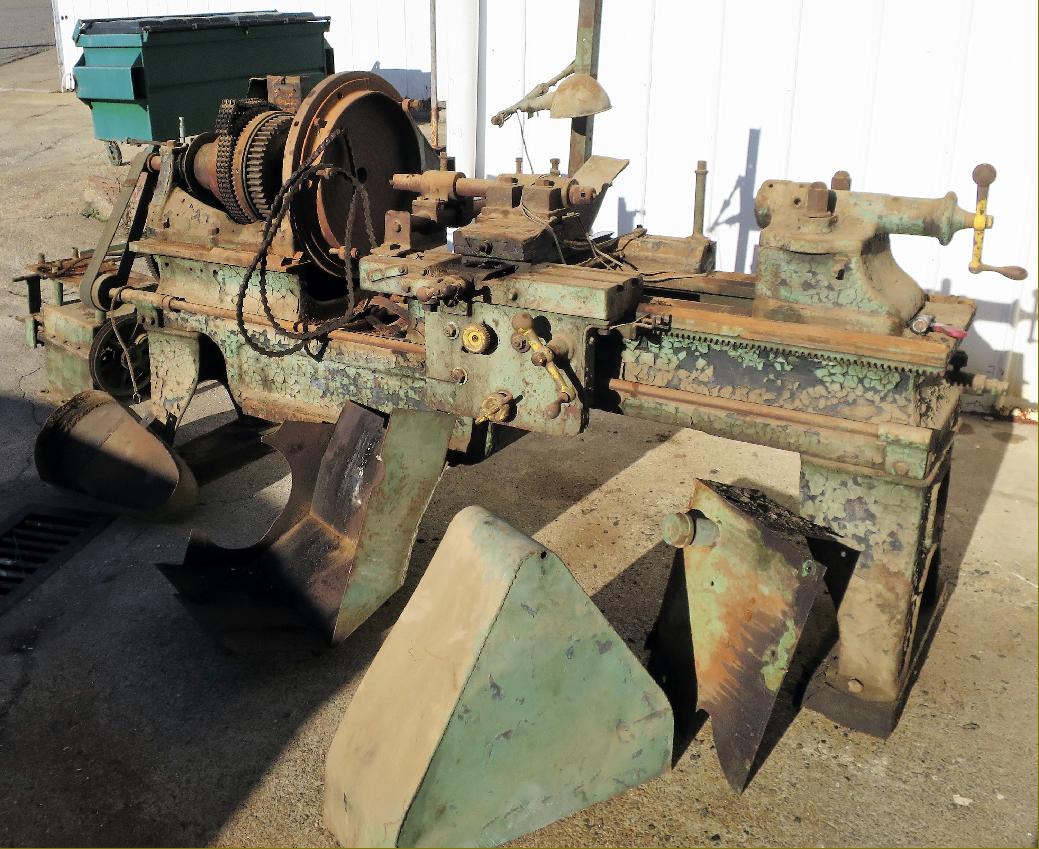
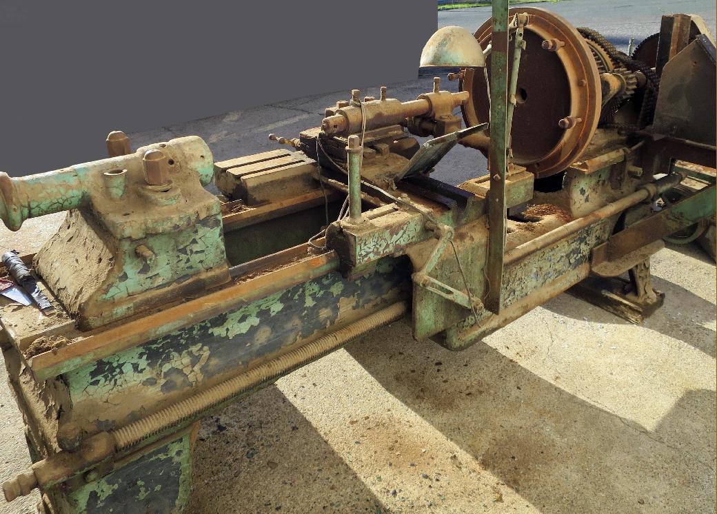
At the turn of the 19th and 20th centuries Edwin Harrington, Son & Co. were based at Seventeenth and Callowhill Streets, Philadelphia, USA, in an area famous for its many machine-tool builders. Although the Company made conventional lathes, they were perhaps better known for their range of "Extension" or sliding-bed lathes. This was not a machine type exclusive to Harrington - many other makers produced similar machines - but Harrington and Son - besides manufacturing Radial and Multiple Spindle Drills and Chain Hoists, appeared to specialised in them and this page illustrate ones produced by the company in the early 1900s. In addition, at the end of the page, can be seen a standard gap-bed Harrington in a derelict condition, as recovered during 2016 from a workshop by the restoration group of the Amador Sawmill and Mining Association in Jackson, California.
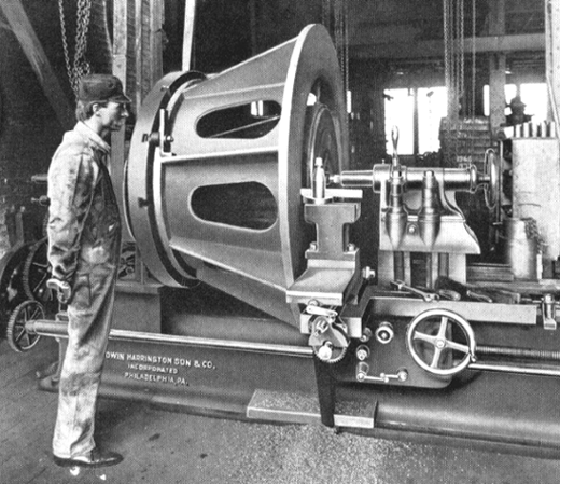
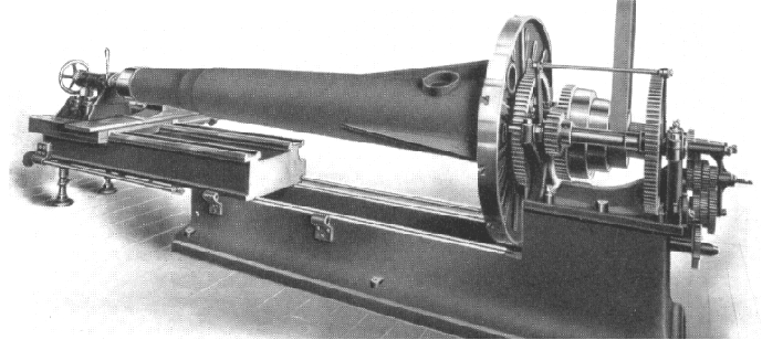
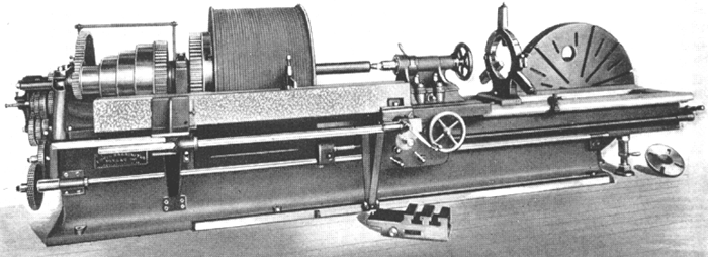
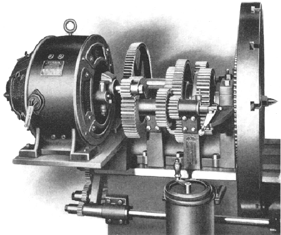
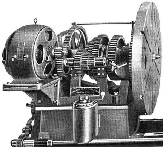
All Harrington sliding-bed lathes had a two-part construction, with the upper arranged to slide on the lower so that the distance between centres, and the width of the gap, could be increased, or decreased, as a particular job demanded. The idea was to combine several machines in one: with the gap closed the machine became a stout, backgeared, screwcutting engine lathe (or 'centre' lathe to British readers) with the capacity for regular work. When the bed was extended, long, thin or irregularly shaped work, perhaps with large diameters at inconveniently placed intervals, could be also be accommodated. This flexibility in sizing and set up allowed smaller engineering shops to take in work which should, nominally, have been beyond their capacity - or in the case of a larger enterprise, would have ensured that the biggest lathes were left free to be used for the heaviest jobs. The Harrington lathes were built in four sizes, named according to the swing above the upper and lower beds, and all were backgeared and screwcutting - the leadscrew being carried by the upper bed and connected to the changewheel drive by a pair of gears, the lower of which was connected to a splined 'power shaft'.
With the makers specifying a countershaft speed of between 45 and 85 r.p.m, and in combination with a "triple-reduction" backgear - an enormous 54 : 1 ratio on the largest lathe - the result was a bottom speed slow enough to allow the successful machining on the outer edges of work up to 5 feet in diameter. In addition to backgear, and the four or five-step headstock cone pulleys, the two smaller lathes each had a two-speed gearchange on the headstock and the larger ones three - giving, in the best cases, a selection of 45 different spindle speeds. The drive could be by either a traditional wall or ceiling-mounted flat-belt countershaft system (or overhead line shafting) or from a built-on variable-speed motor driving direct though exposed spur gears at the rear of the headstock. Quite how the latter system sounded when well worn, and being worked hard, is best left to the imagination.
Of deep section and braced internally by cross ribs, the lower bed carried an upper section sliding in deep guides and constructed with stiffening cross ties placed at frequent intervals. When the required length of top bed had been wound out, the upper and lower sections were locked together by T bolts and the outer, overhanging part of the upper bed supported on two loose screw jacks. On the smallest machine the top section was extended by a screw, with its operating handle positioned at the end of the bed; on all larger versions this drive was augmented by a reduction bevel box to ease the load of moving what was a considerable and very heavy lump of cast iron.
When the top section was extended, and the gap opened, an extra carriage support, fitted as standard, came in to play; positioned under the front edge of the apron, it reached down to floor level where a machined 'way' was formed for it along the lower edge of the bottom bed.
Power sliding and surfacing feeds from a separate power shaft were fitted to all models, the leadscrew only being used when generating threads; power to the feeds was taken through a clutch and gear drive with all the controls grouped exclusively on the apron. As an option, power feed could also be fitted to the top (tool) slide - where it could be made to operate at any angle..
|
|