|
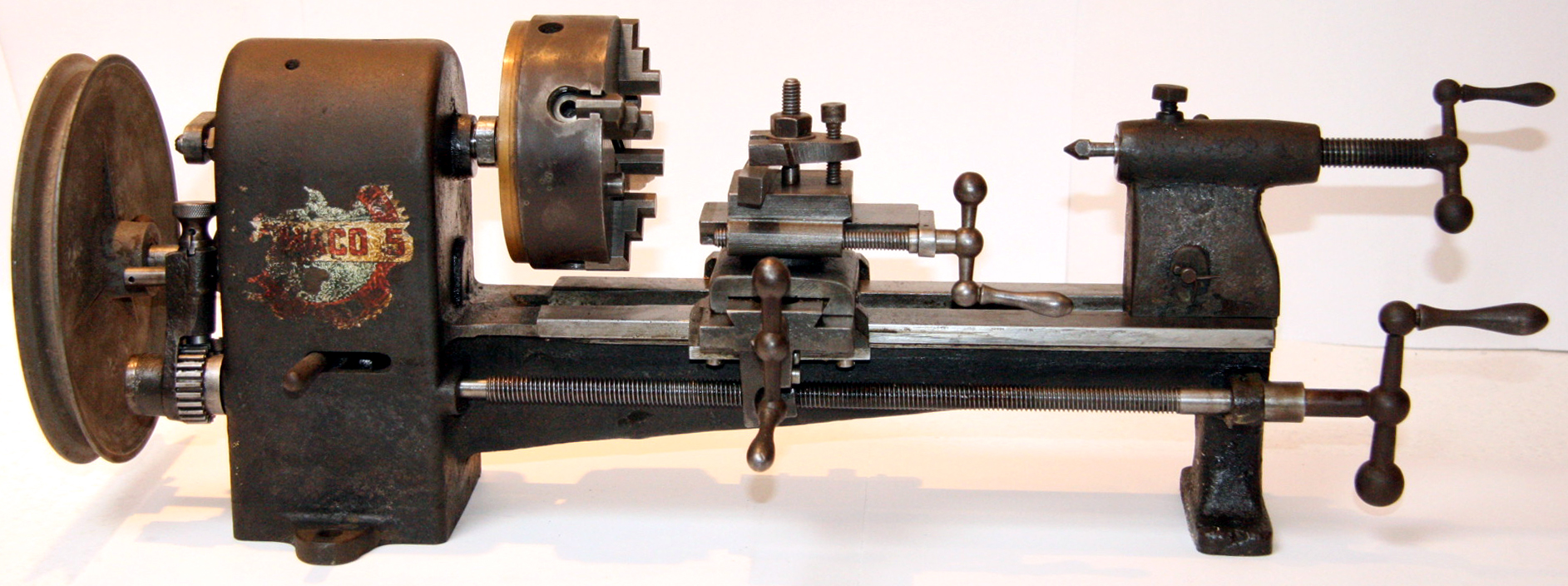
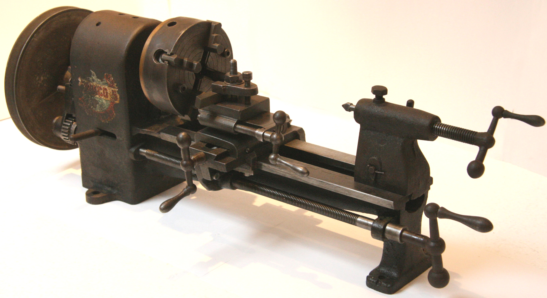
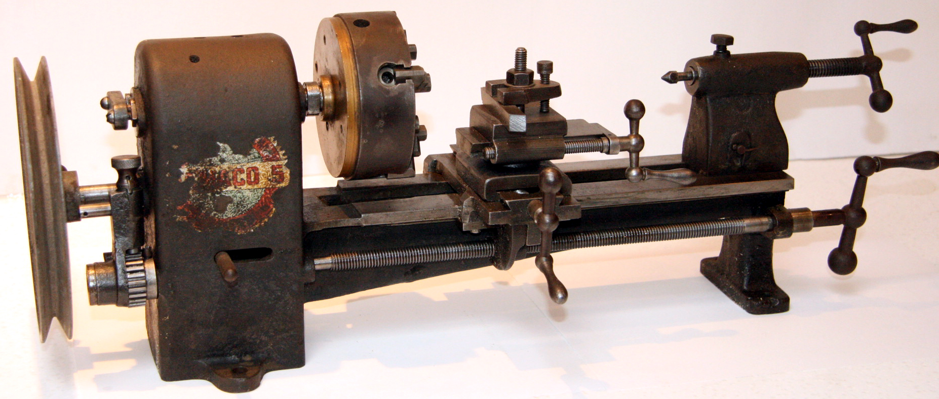
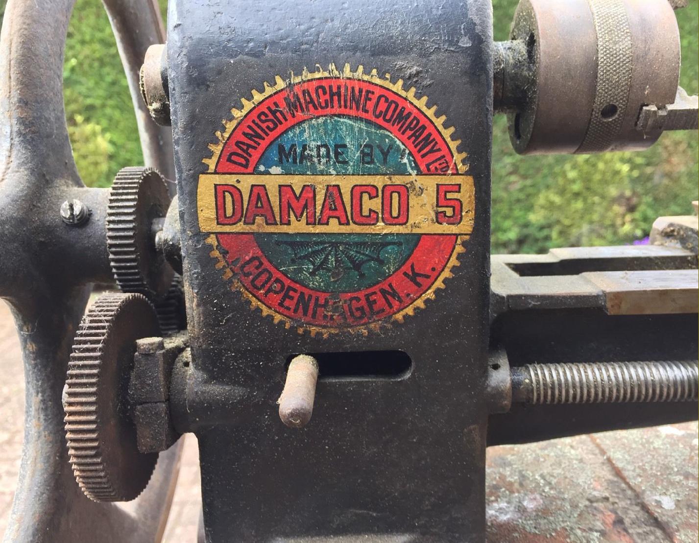
Similar in operating principle to the much lighter Verschoyle lathe, the 2.5" x 8" DAMCO and AM lathes were marketed through W.E.Hughes of 50 & 51, Lime Street, London, E.C.3 and by other major tools suppliers during the 1920s and 1930s. Some versions were badged DAMACO-5 Made By Danish Machine Company Ltd, Copenhagen, K. and others as the AM. Its possible that various brandings were used, for any merchant bold enough to order a large quantity would have been likely to insist upon his name replacing that of the maker. The Danish Machine Co. was established in 1929 by Erik Jespersen, an engineer returning to his native land, having previously emigrated to New Zealand where he had founded, in 1911, the very successful Manawatu Machine Exchange Company (agricultural and machinery repairs) on Rangitikei Street in Palmerston North.
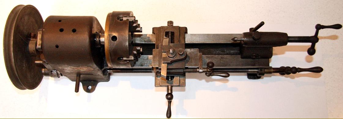
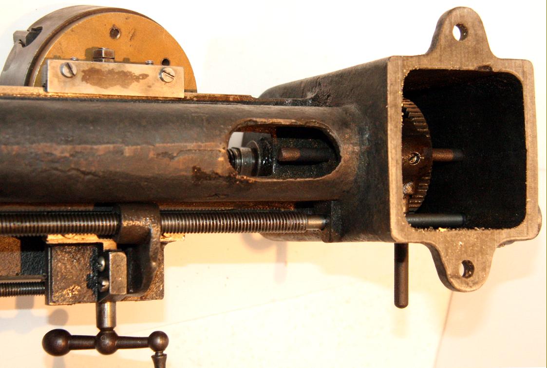
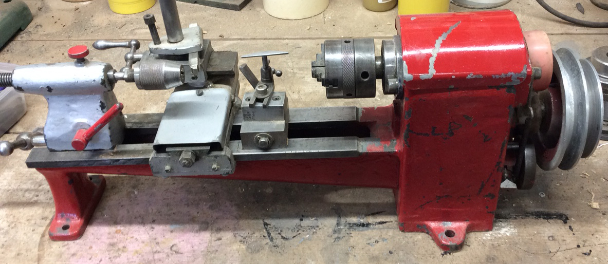
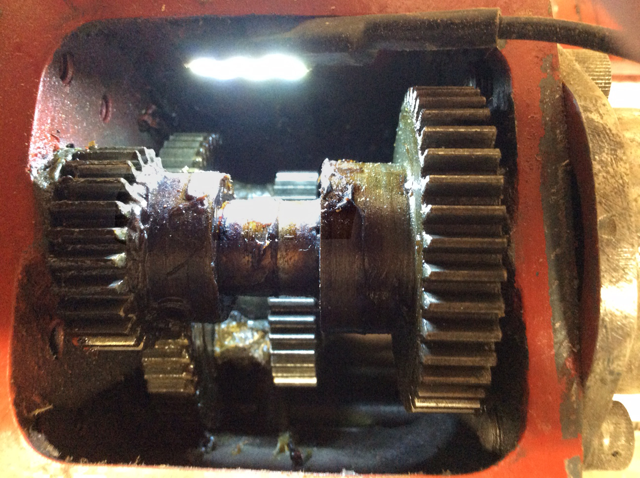
DAMCO/AM was an interesting attempt to market a small, well-specified machine that could be powered in a variety of ways. In the days when a household electricity supply could not be taken for granted, and when small fractional horsepower motors were expensive, DAMCO addressed the problem by fitting their lathe with a large pulley-cum-crank handle that could be turned by hand, a foot-pedal or from a small motor - early versions having one pulley groove, later models being fitted with two, of different diameters, to give an extra speed range. Some models have also been found fitted with a fast-and-loose, flat-belt drive system where one pulley was locked to the input shaft and the other free to rotate upon it. Using a forked striker, the belt could be flicked from one to the other to provide instant control of spindle stop and start. From the input shaft, the drive passed through a two-speed gear, built into the headstock, that provided a step-up ratio to give a higher top speed; the arrangement consisted of a "countershaft" with a pair of sliding gears keyed to it that engage with either of two gears on the mandrel to give either a 1:1 drive (40 tooth to 40) or a 2.2 : 1 (55 tooth to 25) speed increase.
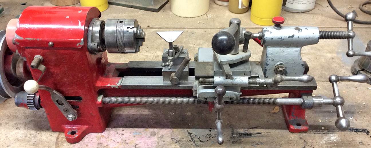
Thus, the DAMCO was a more serious machine than a cursory glance might suggest, for the relatively expensive-to-engineer drive system, together with its heavy cast-iron construction (with bed and headstock formed "as-one") and a very complete specification meant that it sold for a high price: £10 : 0s : 0d being the same as a backgeared and screwcutting Portass Model S on a cast-iron, treadle-equipped stand. However, as was usual with most small lathes at the time intended for amateur use, it could also be specified as a plain-turning model without any sort of automatic tool feed at £7 : 10s : 0d - a considerable saving. In its standard form, it was sold ready to use with a simple, lever-scroll 3-jaw chuck, a compound slide rest, drive plate, centres and treadle gear to provide a means of rotating the spindle.
Running in plain bronze bush behind chuck and direct in the cast iron of the headstock at the other end, the spindle on one lathe examined had a diameter of 14.06 mm -which isn't anything 'nice' in imperial either - and a nose thread of 5/8" x 11 t.p.i.
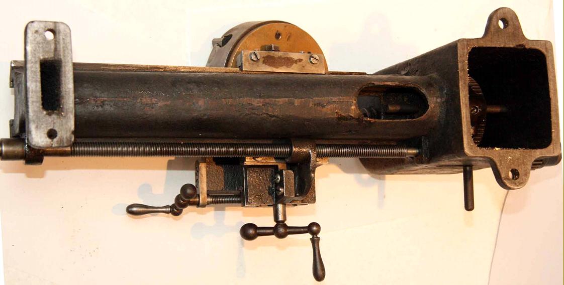
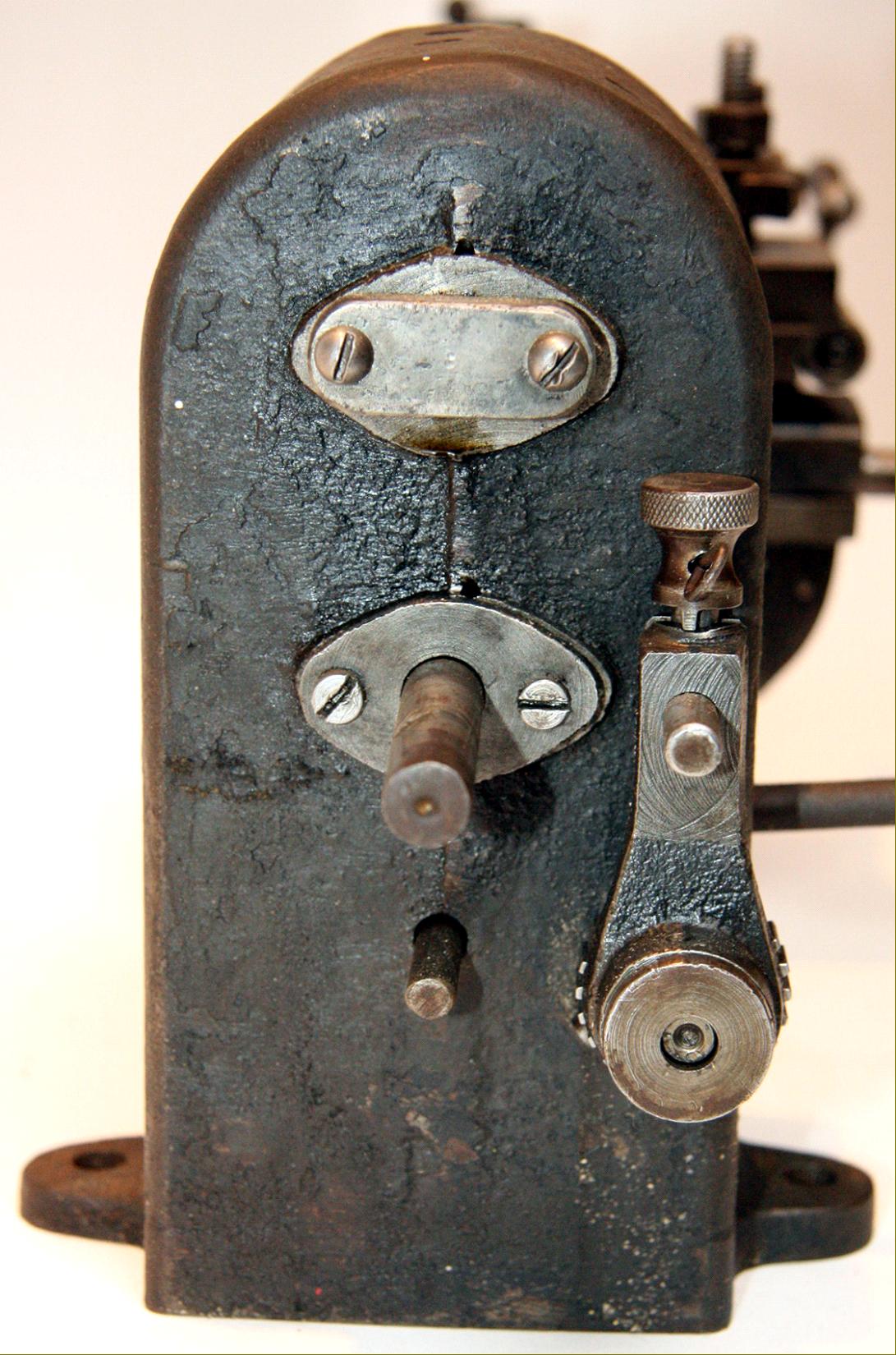
Power-driven, the carriage of early versions was moved in a most unusual and ingenious way. At the headstock end of the 7/16" x 14 t.p.i. leadscrew was a gear, used to provide a "ratcheting" feed, rather in the manner commonly employed on the table of a shaper. The gear was turned by a spring-loaded plunger carried in a cylindrical housing that was rocked backwards and forwards by a miniature crankshaft, driven from an eccentric mounted on the inside face of the drive pulley. The plunger was shaped on its end to either drive the gear when set in one direction, or to slip over it when turned through 180°. Hence, the fitting allowed the feed to be set in neutral - a cross pin through the shaft sat in a grove on top of the housing and allowed the pin the be lifted clear - or engaged by being dropped into mesh. Because a full nut, in cast iron, was fitted to the leadscrew, a dog clutch was provided, built into the headstock with its operating lever protruding through the front face. For hand feeds an unusually large "balanced" handwheel was fitted at the tailstock end of the leadscrew. However, by the mid-1920s modifications had been introduced (as shown in the advertisement below) and the option of a conventional changewheel system was introduced - thus allowing the lathe to become a proper screwcutting type. By an unknown date, but probably the early 1930s, the indexing arrangement appears to have been dropped, and only the changewheel model was offered. Fourteen changewheels were provided that allowed the generation of both English (from 6 to 120 t.p.i) and a range of metric pitches.
Although a proper compound slide rest was included in the price, it was of spindly construction (though probably just adequate for the light forces involved). The unprotected feed screws were just ordinary right-hand Whitworth threads (not square section) of 5/16" diameter by 18 t.p.i. The result was a "cack-handed" operation where turning the handwheel to the right resulted in the slide moving towards instead of away from the operator. This was perfectly fine if just the one lathe was in use, but if a conventional machine was to hand in the same workshop, accidents were certain to occur. There were no micrometer dials and the top-slide screw was set along the edge of its slide, rather than in the middle - a position that would have resulted in an undesirable amount of leverage being applied to the 60-degree sides of the slide's ways and swarf landing on the thread. The cross-slide casting was very short, gave little support to the cutting tool and would have worn the saddle ways in the near and middle sections - and to compound matters, just two coarse-pitch two gib-strip adjustment screws were fitted. Happily, both slide handles - and those fitted to the leadscrew and tailstock - were of the proper "balanced" type, through that fitted to the top slide was rather too large and, by catching on the cross slide when the top slide was swivelled, would have limited the lathe's ability to turn steep tapers.
Three designs of tailstock were used: the second differed from the first only in having a bulge at the end that suggested some form of retaining mechanism for the handwheel drive. However, it was really no different to the earlier type and used a spindle that was nothing more than a length of 12 mm threaded rod terminating in a short plain section with a No. 1 Morse taper socket. As it ran through a 12 t.p.i. thread machined into the body of the tailstock it rotated as it moved in and out - crudeness personified. However, the final design was properly engineered, with a separate, full-length spindle of conventional construction keyed into the housing and driven by a screw passing through its end. All tailstocks had a proper, eccentric clamp and permanently-attached hand lever to lock them to the bed - yet the temptation to save more money was just too great, for the maker, by arranging for the spindle to be crudely clamped by a thumb screw bearing directly against it, a few pennies were taken off the production costs.
If any reader has an AM or Damaco the writer would be pleased to hear from you.
Damco continued here and late-model DAMCO and AM photographs here
|
|