email: tony@lathes.co.uk
Home   Machine Tool Archive   Machine-tools Sale & Wanted
Machine Tool Manuals   Catalogues   Belts   Books  Accessories

Covmac Lathes
Should any reader have a Covmac lathe or literature about
them, the writer would be pleased to hear from you


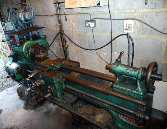
Made by the Coventry Machine Tool Works at St. George's Road, Coventry, England, today the Covmac lathe is rarely found. While the company was not a major player in the lathe market, they were well known for their specialised products connected with the manufacture of nuts and bolts including cold heading, bolt trimming, horizontal forging, thread rolling, screw nicking and "hot-sawing and milling" machines.
Details of the company's lathes are limited but it is known that during the 1930s, and possibly 1940s, just two models were offered: the "13-inch" and "17-inch" - both of almost identical design and construction save for the necessary differences in the castings to accommodate capacity and proportions, the pitch of the leadscrew and the method of drive. Whilst the 13-inch could be had with the option of either an open flat-belt drive or all-geared headstock the 17-inch could only be purchased with the latter specification. The 13-inch model had 39-inches between centres and the 17-inch 60-inches.
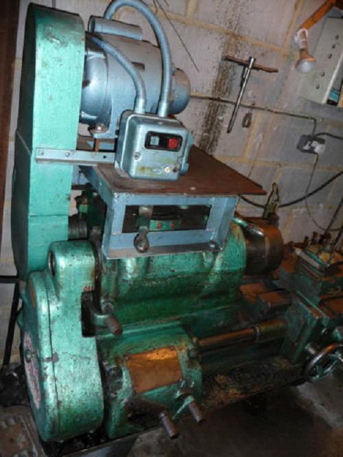
Unusually for an English lathe of the time the bed was of the inverted V and flat pattern with the saddle running on an outer pair of Vees and the tailstock guide by an inner Vee and flat. The catalogue listed a detachable gap bed as standard and, with the bridge section, it provided a maximum turning capacity (on a faceplate) of 28 by 7.5-inches on the 13-inch model and 28-inches by 9.5-inches on the 17-inch. The works would also supply straight bed lathes, or beds of any particular length, providing a minimum of 6 machines was ordered at once. Although the depth of the bed was reduced to the right of the gap, unlike many competing lathes on the Covmac this was not too sudden, and a decent length of full-depth casting was left to improve rigidity. On the 13-inch lathe of both types the bed was supported on simple legs at each end whilst the very much heavier 17-inch stood on a large cast-iron plinth (with a small storage compartment) at the headstock-end and a plain leg at the other.
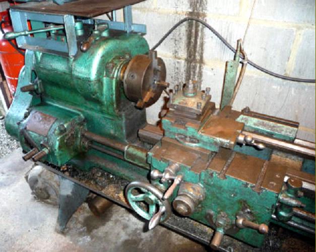
Fitted with a "0.5 carbon steel" spindle of 1.5625-inch bore with a 3-Morse taper and a 6 t.p.i x 2-inch nose thread, the flat-belt drive headstock of the 13-inch model was fitted with plain, parallel gun-metal bearings -
carefully reamed to a jig and finished, where necessary, with the scraper - with that at the front being 2.625-inches in diameter. Each bearing was secured by twin bolts caps and end thrust taken by a ball race. The spindle carried a 3-step cone pulley of considerable width with the backgear assembly incorporating a neat device whereby the spring-loaded plunger that connected the large spindle gear (the bull wheel) to the pulley would, when turned to the engage position, automatically engage itself if the spindle was revolving slowly. Tumble-gears to reverse the direction of the leadscrew were placed inside the headstock, benefiting from the oil splash and away from swarf that had worked its way out through the end of the spindle. The geared headstock of both lathes was, to all intents and purposes, of identical layout but with that for the larger machine having a very much more substantial 2.375-inch bore, 4-Morse taper spindle with a 5 t.p.i  x 3.25-inch nose thread that ran in a 3.625-inch diameter front bearing with a 4-bolt front cap. Unfortunately the bearing construction (with detachable caps) meant that the headstock was completely open at the top with the casting walls having to finish no higher than the centre line of the spindle and a large bolt-on plate being required to seal the assembly. The input shaft was fitted with a single cone pulley and built into it was a toggle-lever operated clutch controlled by a long wooden rod that ran above the whole length of the bed and was thus handy for the operator no matter where he stood.
Headstock gears were all in heat-treated nickel steel with shafts that ran in bronze bearings; lubrication was by splash from a oil sump in the base of the casting. Eight speeds were available controlled by a separate high-low and 4-speed levers mounted on top of the headstock. Unlike the 13-inch, with its tumble-reverse gears on the inside face of the headstock, the geared models had their on the outside in a manner more commonly found on smaller lathes.
Continued below:

Covmac 13-inch cone-drive model

Covmac 13-inch gear-head model

Continued:
Reflecting contemporary practice the drive system was arranged to connect either to the then-common overhead line-shafting or be completely self-contained with a motor sitting on the rearward extension of a specially-modified headstock-end plinth. In either case the 13-inch lathe was fitted with a 9.75-inch diameter by 2.2-inch wide input pulley and the 17-inch a rather larger 11-inches by 3.5-inch version. For the 13-inch lathe a 2.5 to 3 h.p. 750 rpm motor was recommended, and for the 17-inch a 5 h.p. 1050 rpm unit.  The smaller lathe used a V-belt drive from the motor whilst the larger employed a "silent chain", a now-obsolete system often found driving a variety of machinery during the first half of the 20th century. Fitted with the recommended motor and a 2-speed 160 & 300 rpm countershaft the belt-drive 13-inch lathe had 12 speeds from 14 to 445 rpm and the geared headstock version 8 speeds from 17 to 335 rpm.
All models of the lathe were fitted with a screwcutting gearbox as standard that was able to generate 28 different threads and feeds with pitches from 2 to 28 t.p.i. selectable without dismounting or changing any gears. Although this arrangement would have fitted the lathe for most workshop tasks it did mean that special jobs would have been beyond it and, to compensate, the makers offered extra changewheels, including a 127t metric translation wheel, to extend the threading range. Sliding and surfacing feeds were driven by a separate keyed powershaft connected to the leadscrew by a sliding gear just outboard of the gearbox. The shaft passed through two pinion gears in the apron either one of which could be engaged by a quadrant lever to reverse either the sliding or surfacing feed without having to stop the spindle and move the tumble-reverse gears. Feeds were engaged and disengaged by turning a knurled knob in the middle of the apron. The apron was dowelled to the underside of the saddle and of semi-double-wall construction with its open casting bridged by a screw-on plate that gave the two main shafts a bearing at both ends.
In order to allow cutting tools to reach right up to a faceplate with the bed gap piece removed, the saddle was arranged with the cross slide set well over to the left-hand side, the right-hand front wing being used for two heavy-duty T slots. Whilst the cross-slide screw was fully protected from swarf no matter what position the slide was in unfortunately (and all too common at the time) its micrometer dial was of miniscule proportions - and missing altogether from the top slide.
The No. 2 Morse taper set-over tailstock was of the "through-barrel" type and not of a design really suited to the size of lathe. The barrel was locked by a proper compression champ but a loose spanner had to be found to operate the clamping nut.
Supplied with each new Covmac lathe was a 4-way toolpost, a thread-dial indicator, fixed steady rest, faceplate, driveplate and the necessary spanners. A range of options was also offered including a taper-turning attachment; chip tray for the 17-inch (one was standard with the smaller lathe); travelling steady; coolant tank, pump and fittings and draw-in collet attachment.
The 13-inch weighed approximately 1870 lbs and the 17-inch 3360 lbs..

Covmac 17-inch geared-head


Covmac 17-inch showing the extended rear to the headstock end plinth  that formed a motor-mount platforms. The long belt from headstock to base drove the coolant pump.

13-inch headstock with backgear guards and bearing caps removed

Headstock of the 17-inch model showing the dog-clutch engagement mechanism on the main spindle

Carriage assembly with T slots confined to the right-front saddle wing. Note the tiny cross-feed micrometer dial - and the absence of one the top slide.

Sliding and surfacing feeds were driven by a separate keyed powershaft geared to the leadscrew by a sliding gear just outboard of the gearbox. The shaft passed through two pinion gears in the apron either one of which could be engaged by a quadrant lever to reverse either the sliding or surfacing feed without having to stop the spindle and move the tumble-reverse gears.

Rear of the screwcutting gearbox

Optional taper-turning attachment


email: tony@lathes.co.uk
Home   Machine Tool Archive   Machine-tools Sale & Wanted
Machine Tool Manuals   Catalogues   Belts   Books  Accessories

Covmac Lathes
Should any reader have a Covmac lathe or literature about
them, the writer would be pleased to hear from you