 |
|
|
|
|
|
|
|
|
|
|
|
|
|
|
|
|
|
|
|
|
|
|
|
|
|
|
|
|
|
|
|
|
|
|
|
|
|
|
|
|
|
|
|
|
|
|
|
|
|
|
|
|
|
|
|
|
|
|
|
|
|
|
|
|
|
|
|
|
|
|
|
|
|
|
|
|
|
|
|
|
|
|
|
|
|
|
|
|
|
|
|
|
|
|
|
|
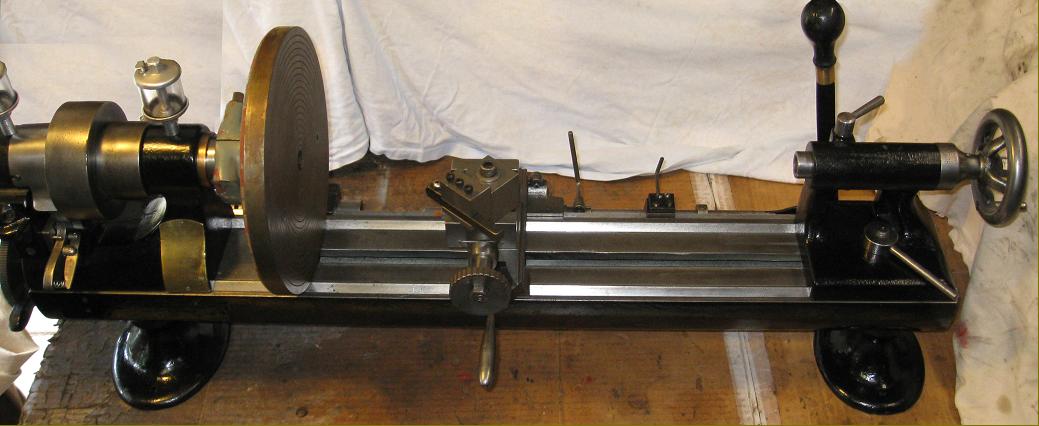
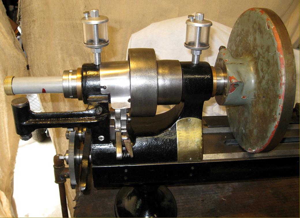
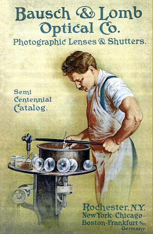
Almost certainly a special machine intended for the manufacture of microscope and telescope parts, this 5-inch centre height bench precision lathe was built circa 1900 to 1910. Manufactured by the famous American optical company Bausch & Lomb it was, although constructed along lines similar to those of competing contemporary American and European makers, in almost every detail rather different and employed a range of novel ideas and a bed having, instead of the usual flat top and bevelled edges, two conventional V-ways to locate headstock, tailstock and carriage - in the manner of the better-known but quite different lathes from Sloan & Chace.
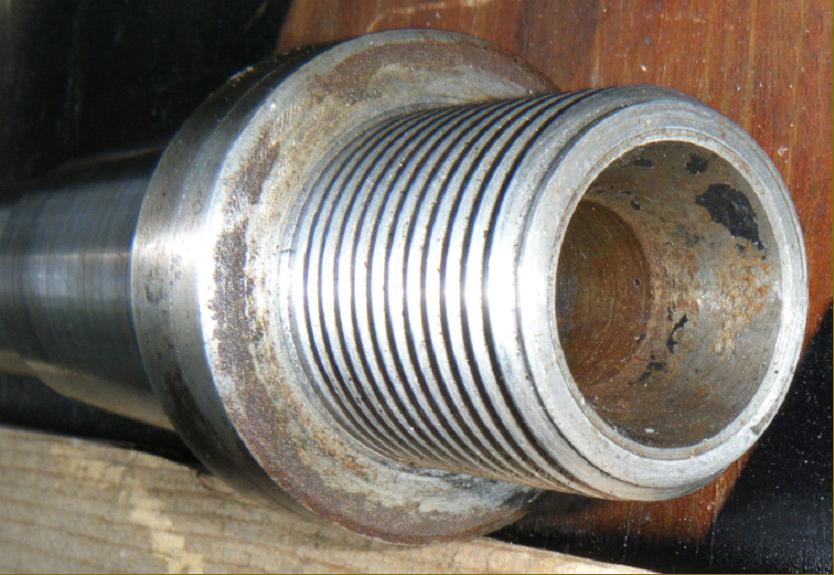
Although one might have expected the spindle bearings to be of the usual type traditionally found on this class of lathe - a hardened spindle running in glass-hard hardened, ground and lapped bearings - the Bausch & Lomb offered a novel solution: opposed tapered bronze bearings with the larger diameter of each to the outside. Because the design could not be assembled with a spindle ground with opposing tapers, the spindle bearings were formed as separate sleeves that used a small key to press lock them to the spindle shaft. The bearing clearance was set by adjusting the gap between the hardened sleeve and bronze bushes, the end of the spindle being threaded and fitted with a "C" spanner nut backed by a split, threaded locking ring. Bored through 14 mm (0.597"), the spindle carried a long, 33 mm diameter by 2.5 mm pitch thread on its nose and had an internal taper to take direct-fitting collets (of a type as yet unknown) with operation by a lever-action closer - unfortunately the only part of this mechanism surviving being the bolt-on bracket for the pivot carrier. Instead of the expected 3 or 4-step headstock pulley, a type with just two was fitted, each unusually wide for the size of the lathe and so a virtual confirmation that this machine was, indeed, intended for use in a production process - a similar 2-step arrangement being used on the headstocks of the W.H.Nichols and Ames "three-bearing" lathes. The drive would have been picked up from a multi-speed, overhead line shaft (and shown in the photograph of the Bausch & Lomb factory below) with fast-and-loose pulleys arranged to act as a clutch.
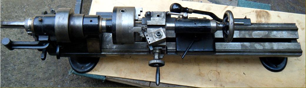
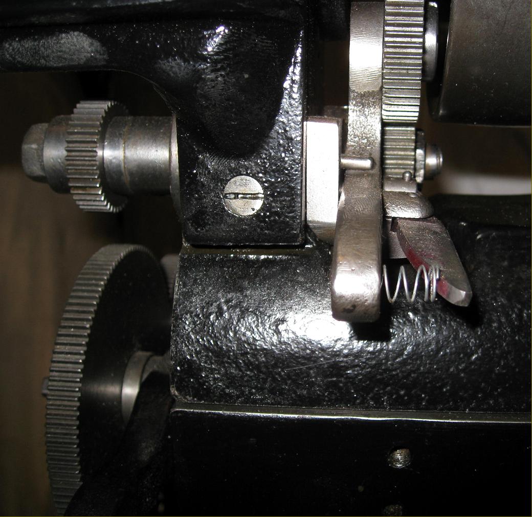
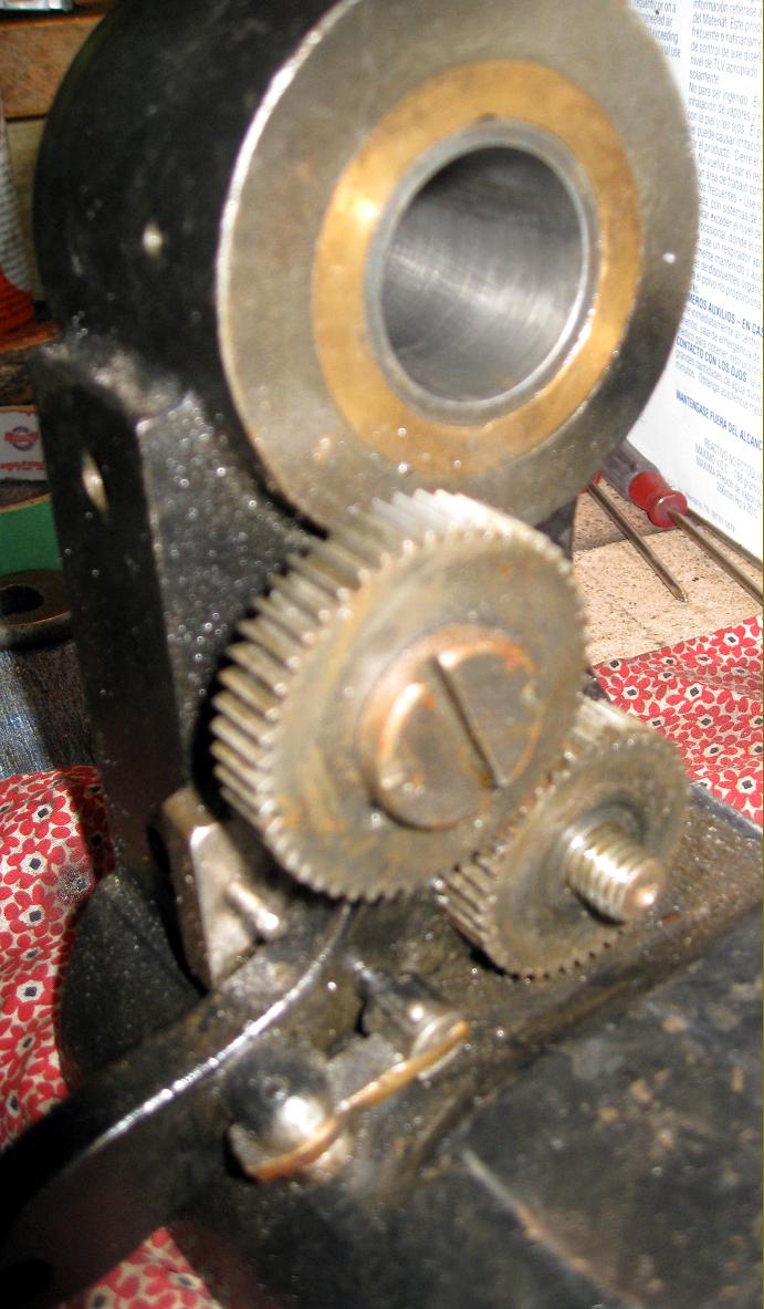
Another highly unusual feature was the arrangement of the hand feed and screwcutting drive to the carriage - the latter using a conventional tumble-reverse mechanism (with a neat, sprung lever originally in bronze) located not on the outside, as might have been expected, but carried on a plate screwed to the inside face of the headstock beneath the left-hand spindle bearing. Driven by a gear mounted on the spindle to the left of the larger headstock pulley, the drive passed through the headstock wall to a screwcutting gear train, held on a slotted arm pivoting from a boss bolted to the rear of the bed. From there the drive continued as a long shaft, running along the back of the bed, that held the "master thread" - this part of the arrangement being a form of chase screwcutting attachment - apparently designed specifically for the manufacture of optical instruments and able to cut longer-than-normal thread lengths. However, on the lathe shown below there is no follower fitted to engage the thread - and details of how this might have been arranged are uncertain. The carriage could also be driven along the bed by a hand-operated lever positioned towards the tailstock end, the various elements (of both screwcutting and hand feed) being adjustable along a dovetail section machined into the back of the bed and locked to it by clamps. As both feeds could not be used simultaneously, each was connected to the back of carriage by an easily released rod-and-socket joint.
To engage screwcutting the cross slide was lifted (there were no keeper plates at the front to secure the saddle to the bed and the front of the slide was extended to form a handle, with a hinge positioned at the back) and the cutting tool brought to bear on the workpiece. How the slide was held in the elevated position and the cut adjusted is uncertain (most similar systems have at least an adjustable stop screw that abuts something solid) and possibly parts are missing from the example illustrated. Another item lost from the lathe below is the headstock-mounted tool tray (these can be seen in the Bausch & Lomb factory photograph) - but the four holes (on 4.65" centres and threaded M6 x1) used to secure it are present.
Should any reader have a similar lathe or other special machine by Bausch & Lomb, the writer would be interested to hear from you.
|
|
|
|
|
|
|
 |
|
|
|
|
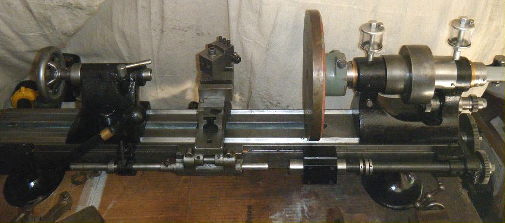
Bausch & Lomb precision bench lathe circa early 1900s
|
|
|
|
|
|
|
 |
|
|
|
|
|
|
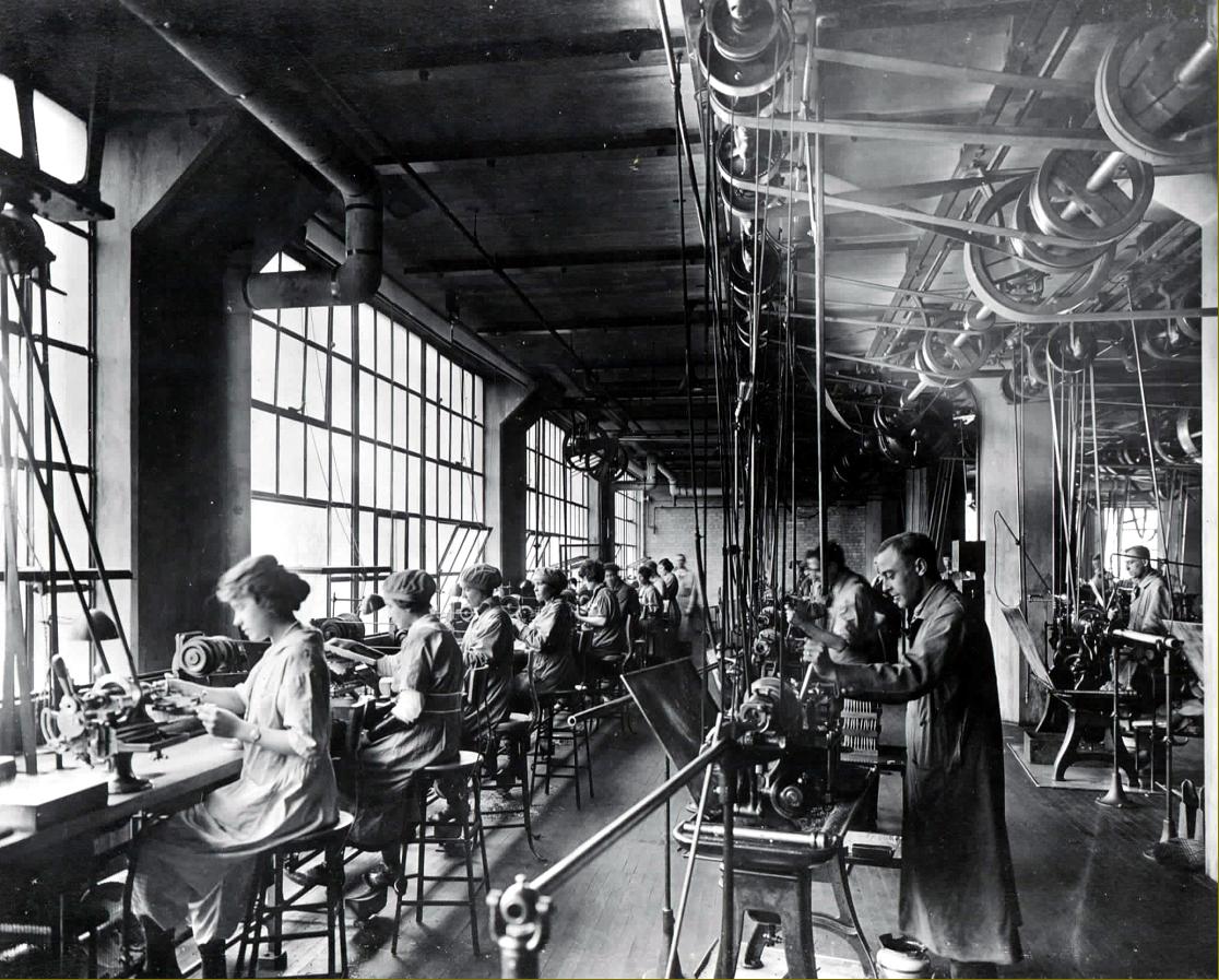
Inside a section of the Bausch & Lomb factory: on the left a line of girls working at bench precision lathes - probably made by Bausch & Lomb (the tool trays are in position and differ in shape to those used on Cataract lathes). To the right are rows of small capstan lathes by an unknown maker. Note the conditions, typical of a 19th century workplace: deep windows (possibly north facing for maximum light without sun glare) and the complex overhead line shafting. Picture courtesy Bausch & Lomb
Additional Bausch & Lomb factory photographs here
|
|
|
|
|
|
|
 |
|
|
|
|
|
|
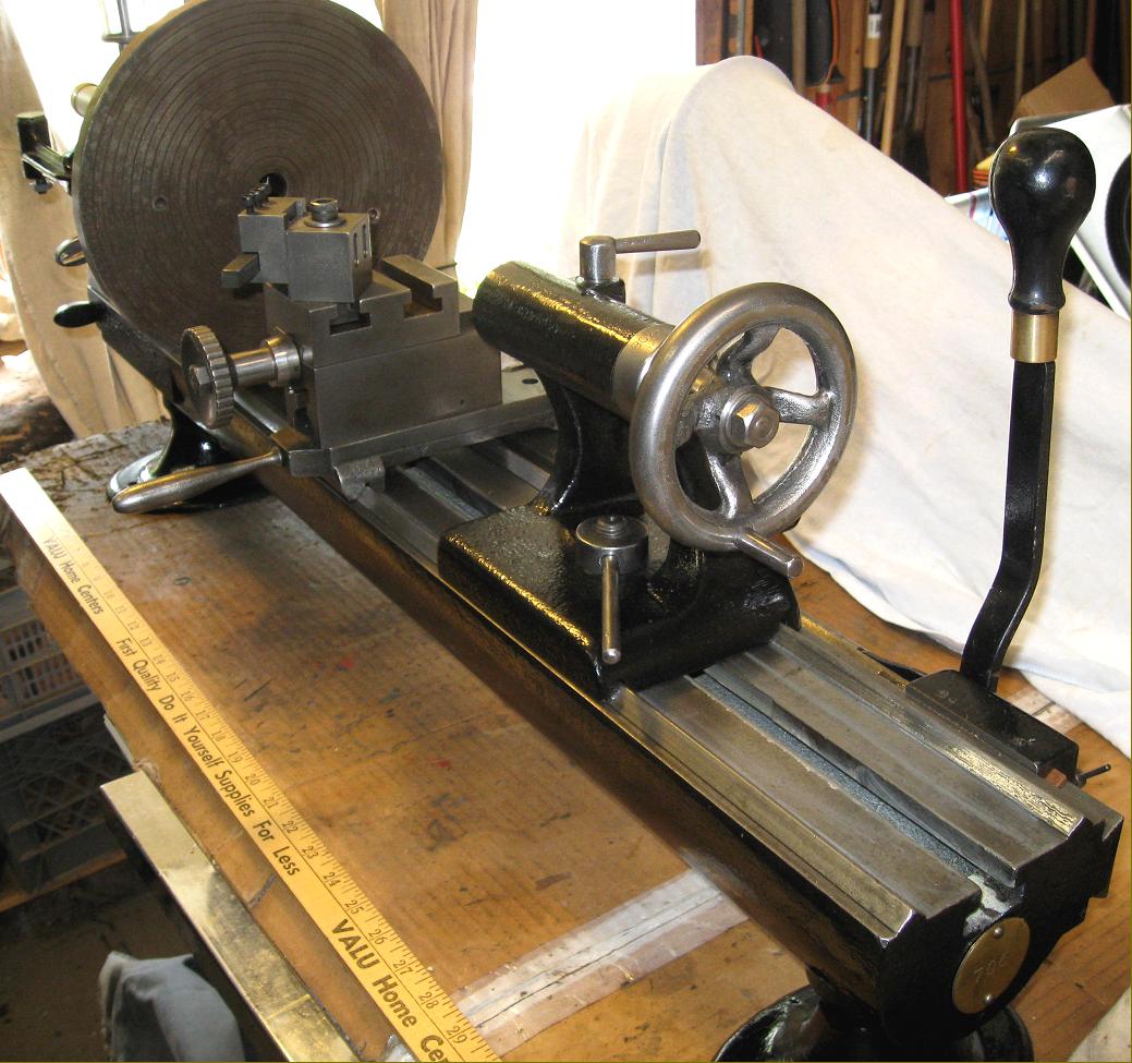
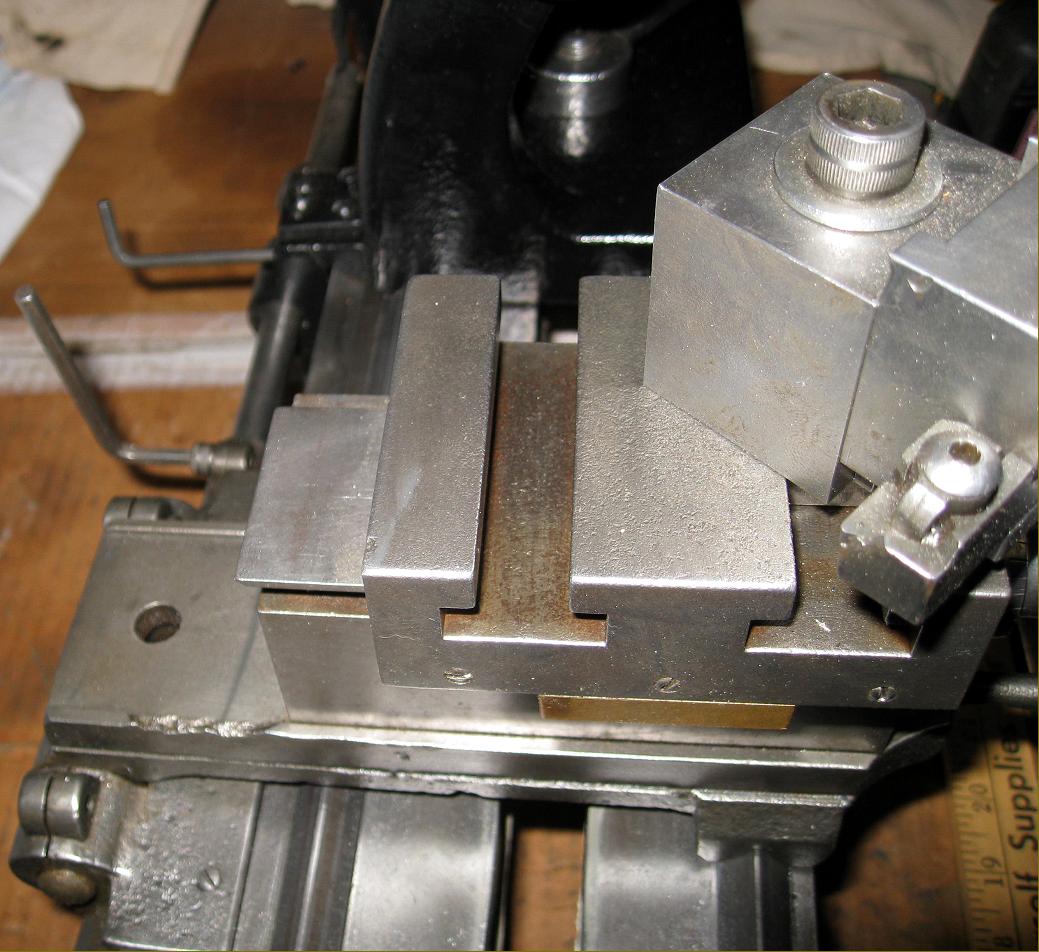
A view showing the unusual (for a bench precision lathe) twin V-way bed - only the Sloan & Chace having a similar arrangement. Clearly visible is the handle extension to the front of the saddle that allowed it to be hinged upwards for screwcutting duties
|
|
|
|
|
|
|
|
|
|
|
|
 |
|
|
|
|
|
|
The saddle hinged fully back
|
|
|
|
|
|
|
 |
|
|
|
|
|
|
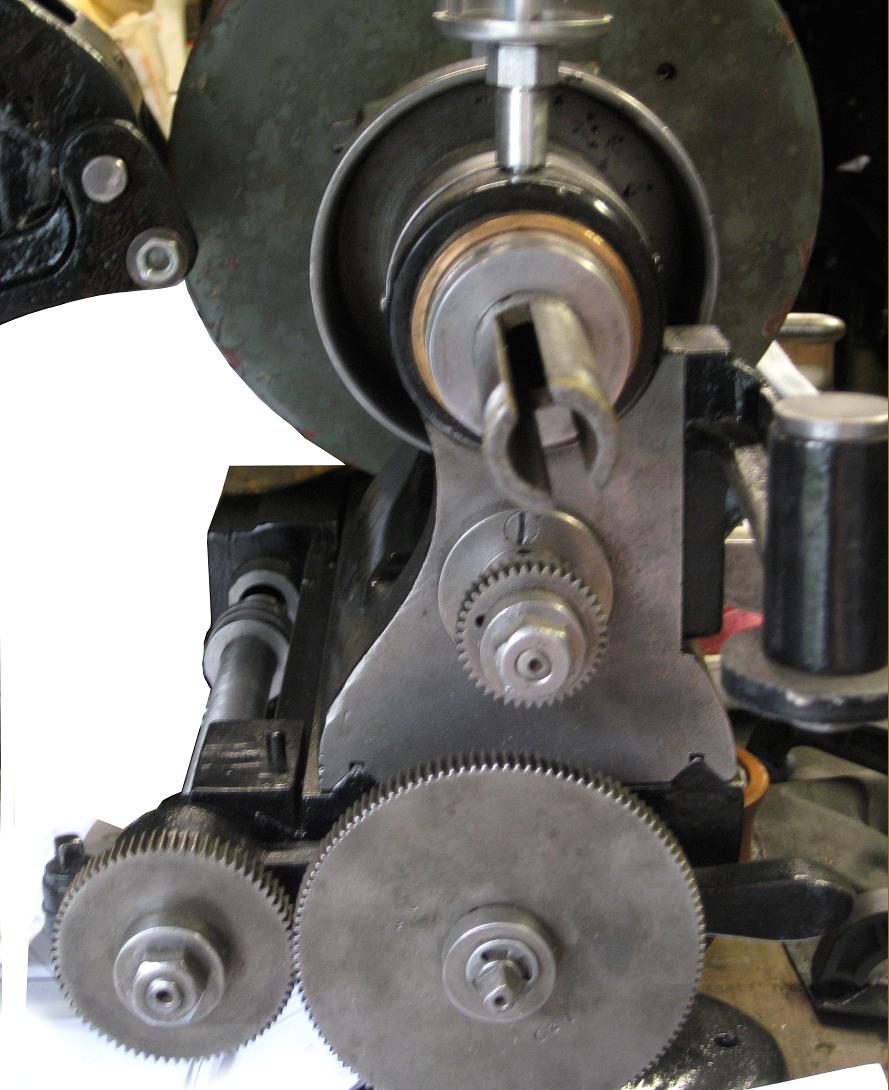
Instead of the expected 3 or 4-step headstock pulley, a type with just two steps was fitted - indicating that the lathe was almost certainly intended for use in a production environment. Note the highly unusual screwcutting arrangements, with gears, inside the larger headstock pulley, connected to a tumble-reverse mechanism that drove a set of changewheels mounted on a slotted arm pivoting from a boss bolted to the rear of the bed. Fitted to the back of the bed, and running along it, was a novel form of chase screwcutting attachment, possibly of a special design for the manufacture of specific optical instruments.
|
|
|
|
|
|
|
 |
|
|
|
|
|
|
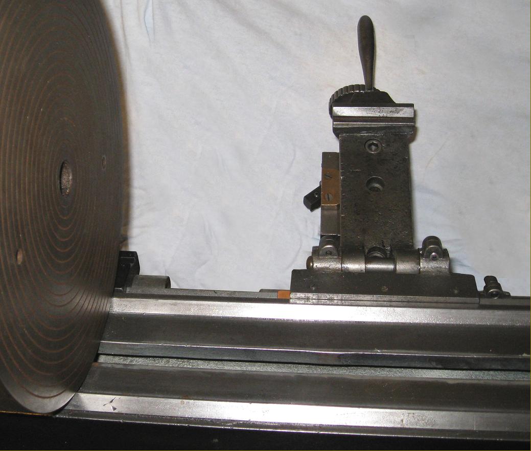
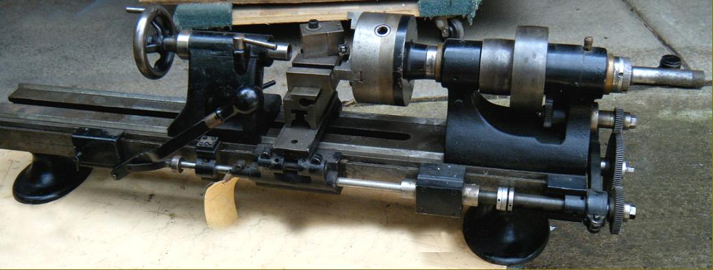
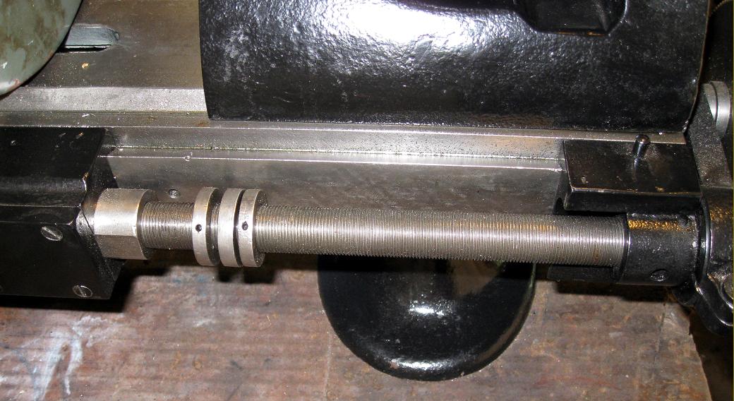
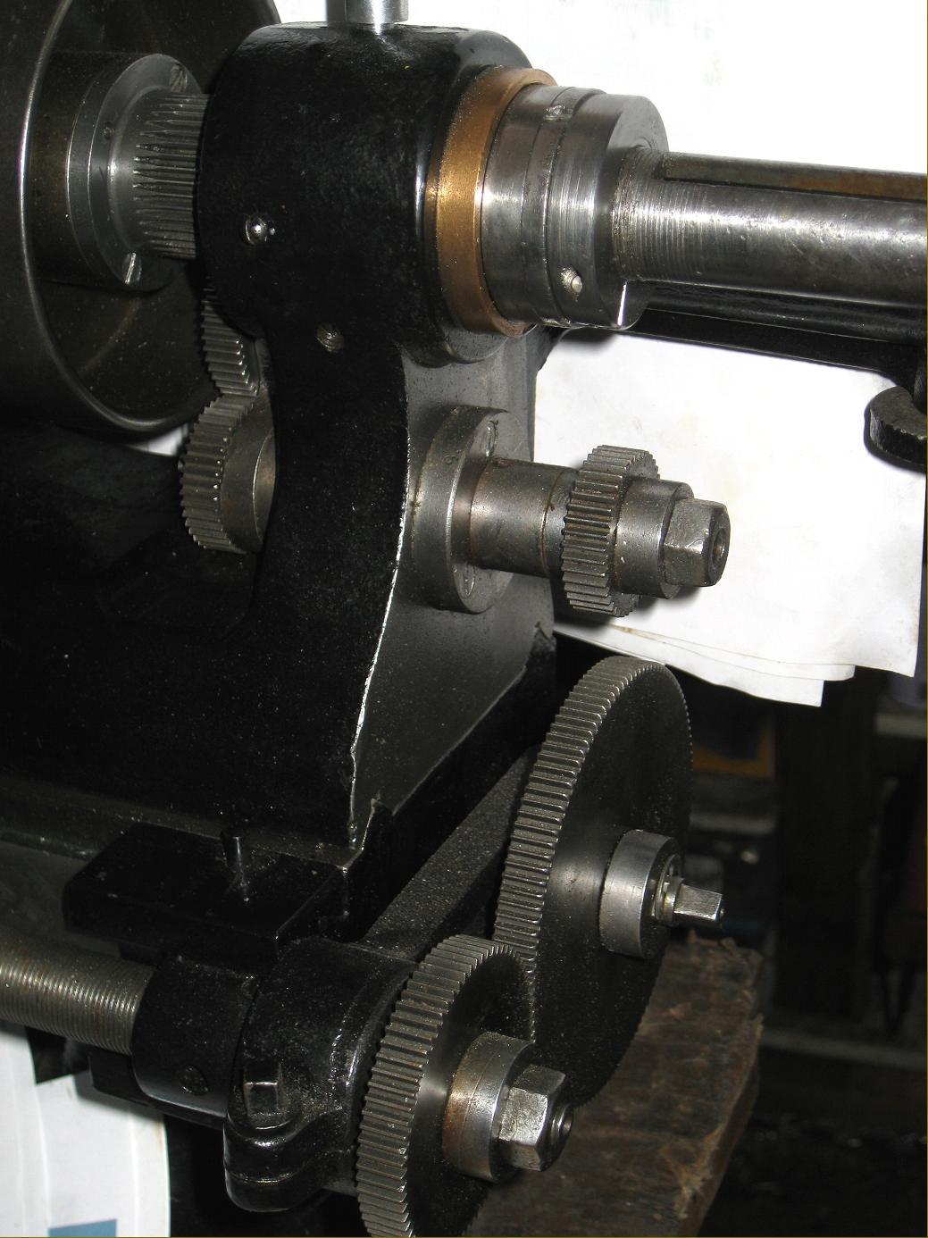
Bausch & Lomb fitted with chase screwcutting attachment of a special form almost certainly intended for the manufacture of specific microscope and telescope components. To allow the carriage to be driven along the bed by either a hand-operated lever or the screwcutting mechanism, both elements were carried on a long dovetail section machined into the back of the bed, the individual components being locked to it by clamps and the feeds locked to the carriage by rod-and-socket joints.
|
|
|
|
|
|
|
 |
|
|
|
|
 |
|
|
|
|
 |
|
|
|
|
 |
|
|
|
|
|
|
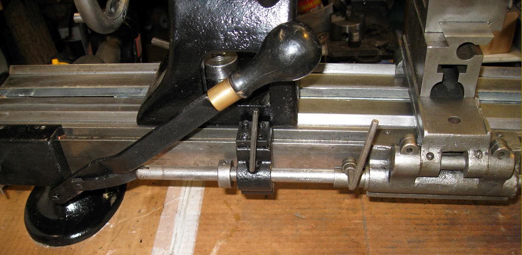
A rod-and-socket joint was used to connect the hand-operated feed o the carriage
|
|
|
|
|
|
|
 |
|
|
|
|
 |
|
|
|
|
 |
|
|
|
|
|
|
A plate, screwed to the inside face of the headstock beneath the left-hand spindle bearing was used to carry a tumble-reverse mechanism
|
|
|
|
|
|
|
 |
|
|
|
|
 |
|
|
|
|
|
|
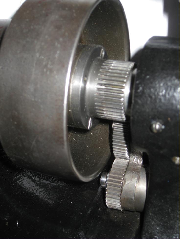
Drive from the headstock spindle mounted gear to the tumble-reverse mechanism
|
|
|
|
|
|
|
 |
|
|
|
|
|
|
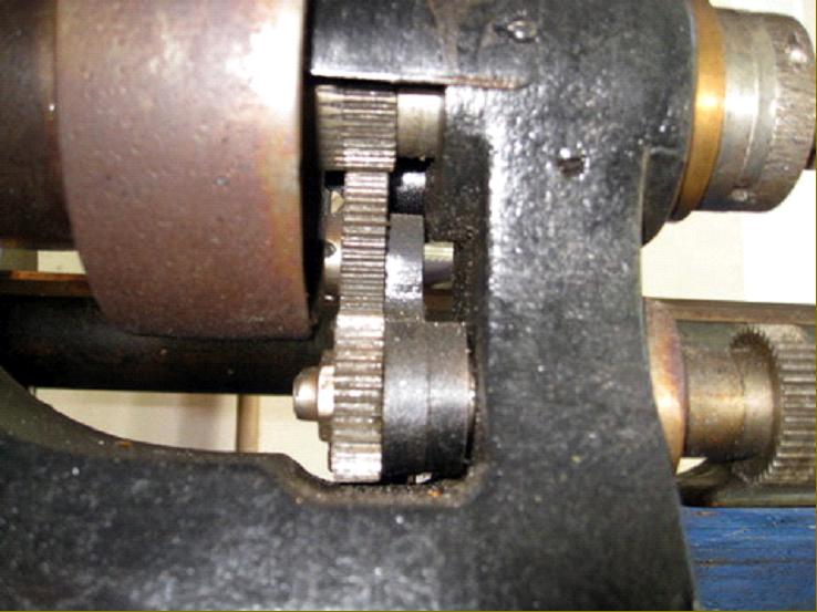
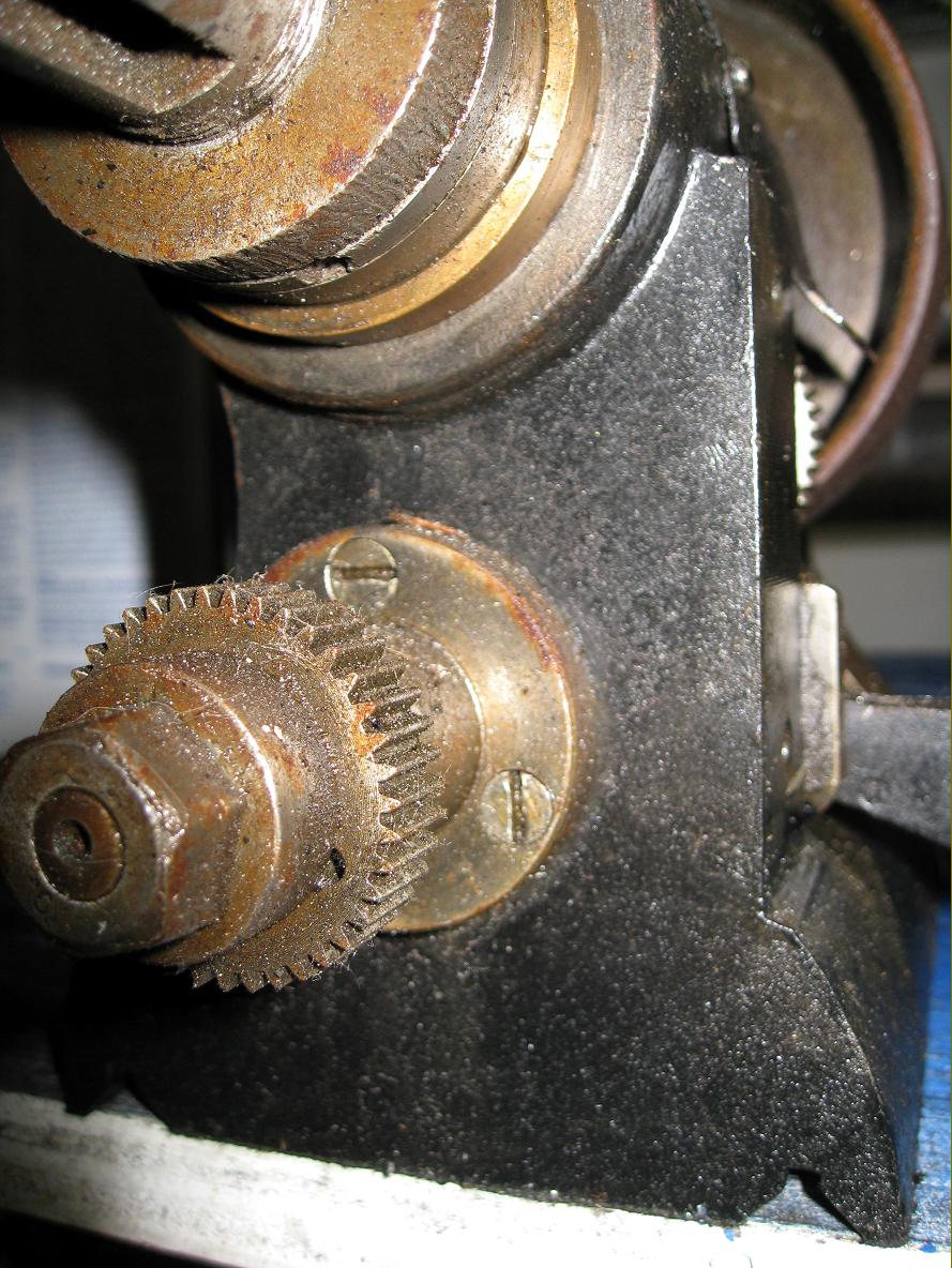
Final drive gear on the inside of the headstock casting. The pointed teeth indicate a long and useful life…...
|
|
|
|
|
|
|
 |
|
|
|
|
|
|
Stud gear on outside of headstock casting used to drive the screwcutting changewheels
|
|
|
|
|
|
|
 |
|
|
|
|
 |
|
|
|
|
 |
|
|
|
|
|
|
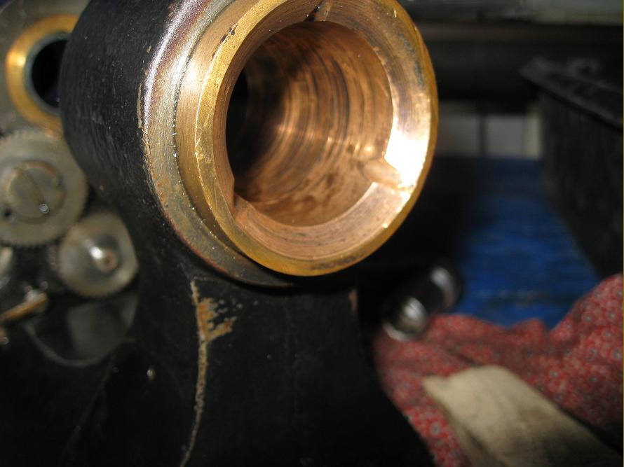
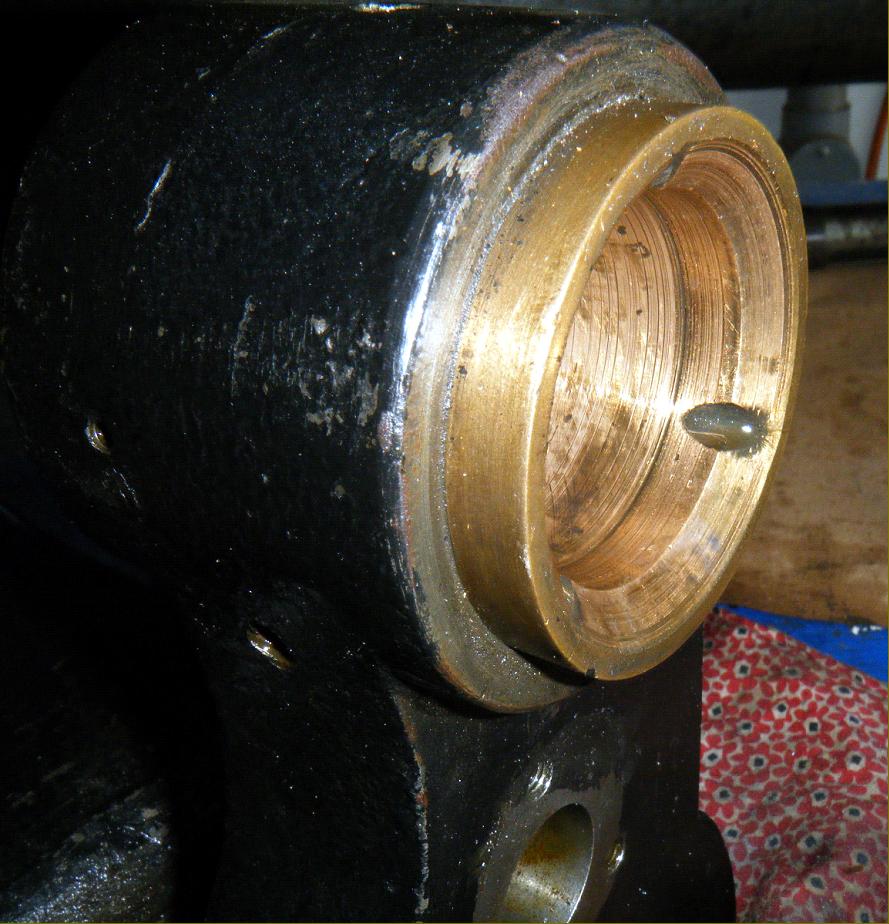
Front tapered bearing less the hardened bearing sleeve into which the spindle fitted
|
|
|
|
|
|
|
 |
|
|
|
|
|
|
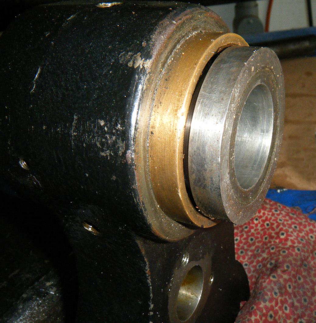
Outside face of the left-hand bearing. The tapered bearings faced each other, in opposition, to give the best possible support
|
|
|
|
|
|
|
 |
|
|
|
|
 |
|
|
|
|
|
|
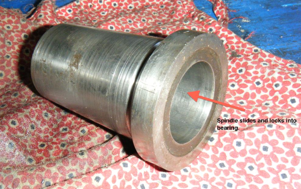
Hardened and tapered sleeve fitted to the left-hand bearing and awaiting the spindle
|
|
|
|
|
|
|
 |
|
|
|
|
|
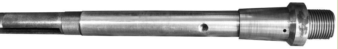
Spindle fitted with its front hardened and tapered bearing sleeve
|
|
|
|
|
|
|
 |
|
|
|
|
|
|
|
|
|
|
 |
|
|
|
|
|
|
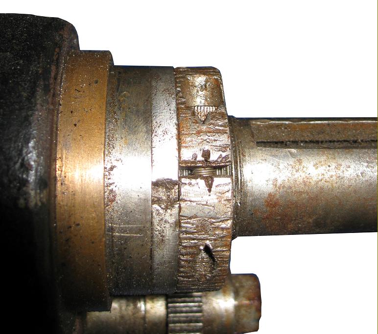
Bearing clearance adjustment ring and locking sleeve
|
|
|
|
|
|
|
 |
|
|
|
|
|
|
|
|
|
|
|
|
|