|
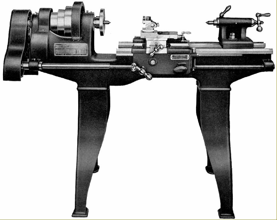
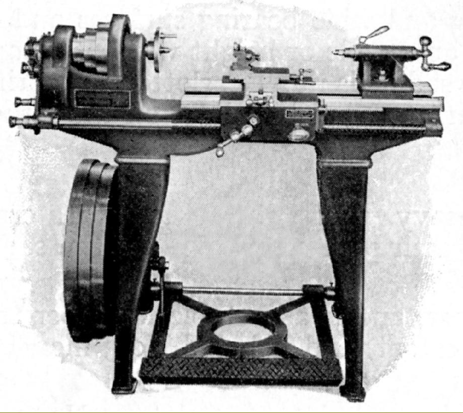
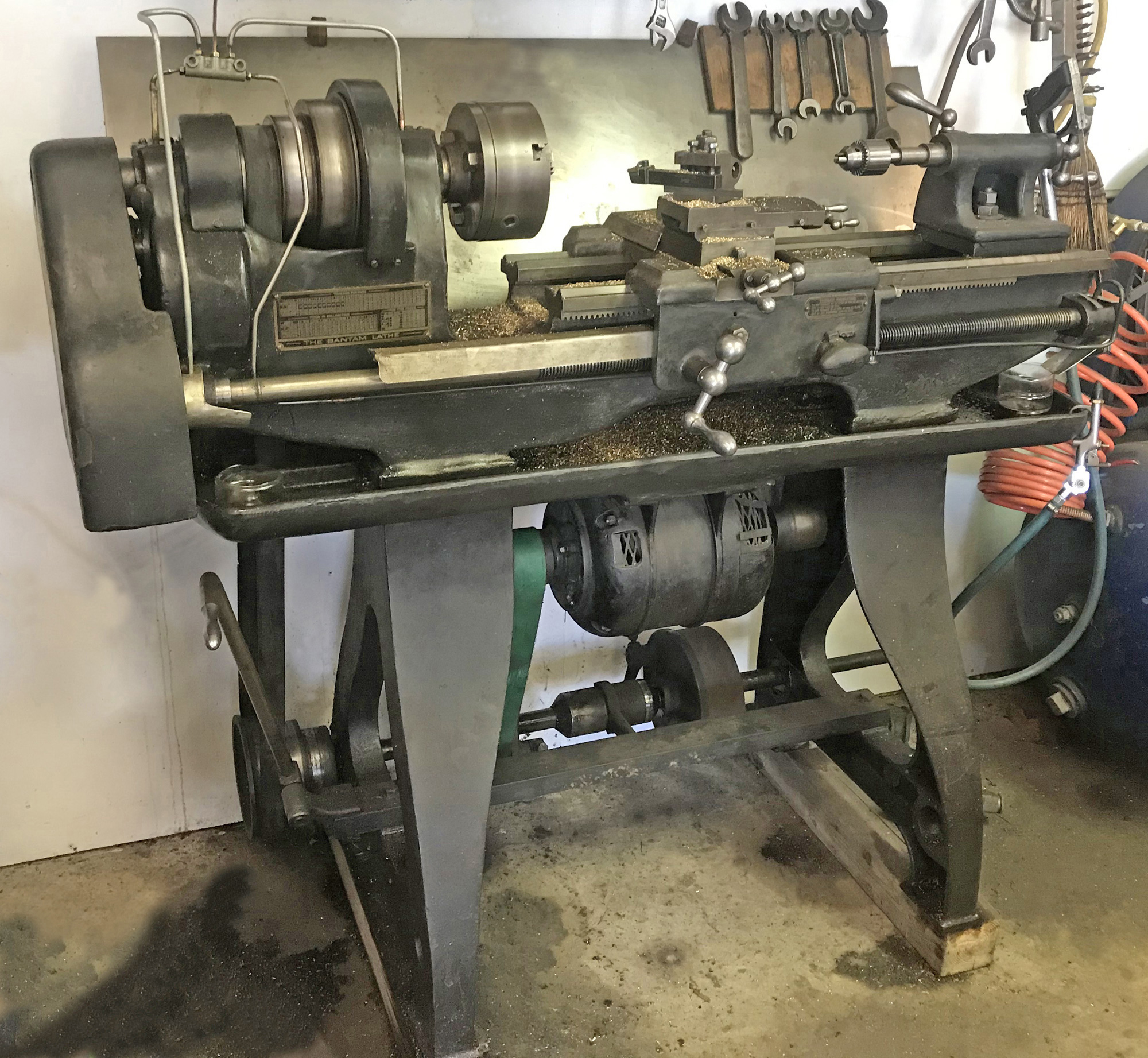
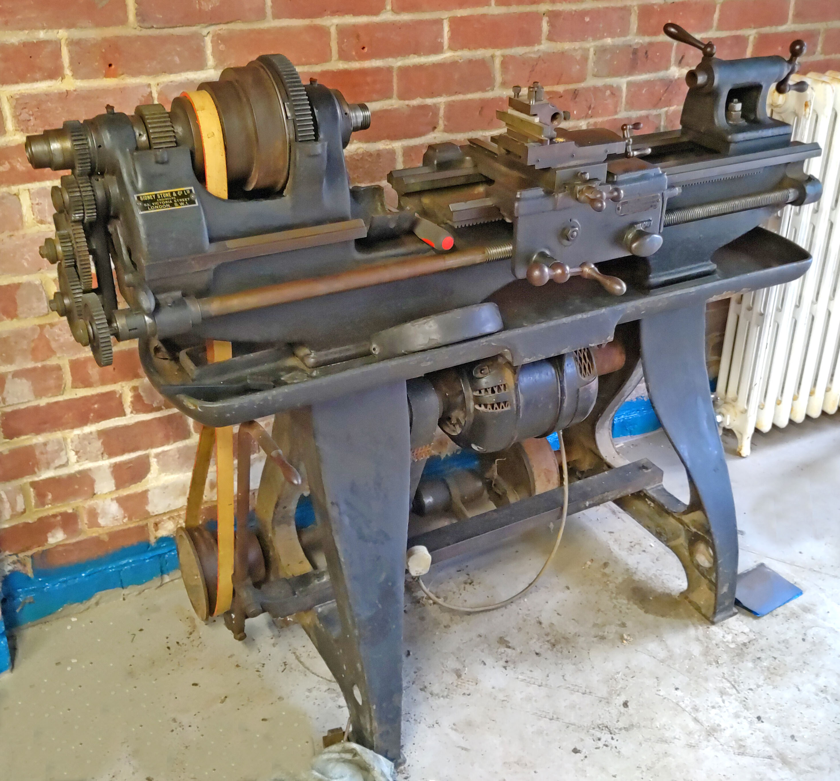
Unlike other pre-WW2 Colchester Models (Master, Triumph and Mascot) that had been offered with either a geared headstock or flat-belt drive, the 5" x 24" gap-bed, backgeared and screwcutting pre-WW2 Bantam was sold only in the latter form as a basic lathe for coupling to an overhead line-shaft drive system or, at what would have been considerable extra cost, complete with a treadle and flywheel assembly for use in locations that lacked a power source. The designer of the stand and treadle must have been concerned to get as much mass into the system as possible for, not only was the flywheel suitable heavy, but the cast-iron footplate of the treadle unit also of great weight.. By the middle of the 1930s, it could also be had equipped with what the makers ambitiously referred to as a "self-contained" motor drive - in reality, a rather clumsy and (even by then) old-fashioned countershaft system bolted at floor level to the back of the legs with the 0.5 h.p. 3-phase motor suspended under the heavy cast-iron chip tray. With a 1425 r.p.m. motor the assembly allowed (with backgear), six speeds from around 28 to 450 r.p.m. The drive was equipped with two clutches, one turned by a "straight-run" belt for forward speeds and the other by a "crossed-belt" to give reverse. By this means the spindle could be stopped, started or reversed with the motor running; the mechanism on this type of drive complied with contemporary safety regulations and was shielded by wire-mesh guards.
All main castings were in close-grained grey iron, alloyed with steel, rough machined and then seasoned to relieve stress before being finely machined. The cross-braced, traditional-pattern Colchester bed was unusually wide for a 5-inch lathe and finish ground - as were all the other sliding surfaces - with the carriage running on front and back inverted Vees and the tailstock on a central V and flat. With the standard faceplate fitted a piece of material up to 3-inches thick and 14-inch in diameter could be turned in the permanently-open gap.
Cast as one with the bed to aid rigidity the headstock held a high carbon steel 0.75-inch bore spindle running in parallel-bore bronze bearings (the front some 1.75-inch in diameter by 2.75-inch long) and carried three cone pulleys 6, 51/4 and 4-inches in diameter driven by a 13/8" wide belt. The 1.5-inch by 8 t.p.i. spindle nose carried a ground register behind the thread (a refinement still not universal at the time); thrust was taken care of by a ball race and the 7 : 1 ratio backgear mounted under the spindle line, giving a very compact and rigid arrangement.
Screwcutting was by changewheels, through an external tumble-reverse mechanism and without the option of a gearbox; pitches from 4 to 60 t.p.i. could be generated by the standard 14-gear set with the inclusion of a 127t transposing gear allowing a range of metric pitches to be cut as well. The 6 t.p.i Acme-form leadscrew that was cut from a master certified by the National Physical Laboratory with the December 1931 certificate (.. Examination of the Pitch of a Leading Screw) proclaiming that, at 67°F, the pitch of the master was accurate to within 0.0002" over any 12-inch section and better than 0.003" over 36 inches - measured on either side of the thread flank. According to the test certificate, the "master" leadscrew held by Colchester to check their production units was 2.5-inches in diameter, 113-inch long with a 69-inch threaded section with a: "square-thread cut with a right-hand pitch of half an inch". However, all was not good news for the paperwork added: "On removing the screw from the accurately aligned half-bearings in which it had been threaded, it was found that the screw had developed a permanent set of nearly 0.02 inch at the centre." Even so, once the leadscrew had been accurately set up on a testing bench, with the axis of the threaded section carefully aligned, the errors were still inside the stated limits except for the first 12 inches - which was out by just 0.0001".
Using a decently-long saddle (though without T-slotted wings) the carriage assembly was a simple affair with no power cross feed and open gears to provide a reduction between the carriage-traverse handwheel and the bed-mounted rack. The leadscrew clasp nuts were operated by an oval handle the frankly silly design of which did nothing to help oily hands get a grip.
On early lathes, only the cross slide was fitted with a (small) micrometer dial but the top slide could be rotated through 360 degrees - and was locked by screws that passed through the cross slide to bear against an inverted conical spigot. One option was a proper, full-size T-slotted boring table that simply slide on in place of the ordinary cross slide. The standard toolpost, resembling that fitted to the Round Bed Drummond, could be rotated to any position and held tools in a choice of a rectangular slot or round hole.
With off-set available on its sole plate for taper turning, the tailstock and had a ground-finished, No. 3 Morse taper barrel with self-eject.
Supplied as standard with the lathe were the following: faceplate, travelling steady, two No. 3 Morse centres, a thread-dial indicator, 14 changewheels, tables for Whitworth and metric threads and the necessary spanners. Unfortunately, on one example examined (though all may not have been so equipped), the metric section of the brass thread-cutting chart contained an error in the arrangement of the changewheels..
|
|