|
Little is known of the origins of the Artisan Manufacturing Co, of 839 West Sixth Street, Cincinnati, Ohio, USA but - should the design of their 5-inch centre height lathe illustrated below be a guide - they must have produced some interesting machine tools with unique combinations of seldom-seen features. The earliest mention of the Artisan dates from 1923 in the magazine "Belting and Transmission" where it was described as, "An attractive proposition for the dealer who sells to the garage, Service Station and Small Shops". A second, more complete advertisement ran in the "Industrial Education" magazine of 1924 where it was claimed, "It was designed to meet the needs of the general machinist, tool maker, garage mechanic, gunsmith, electrician, amateur, and wherever a small lathe is required. Its radically new design makes possible its very low price. It has a swing of 11 inches with 24 inches between centres, and is driven by a 1.2 h.p. motor…"- The final known mention is in a 1927 edition of the "American Blacksmith and Motor Shop" where some more relevant and interesting details were listed including, "...16" swing over the gap, 1 5/16" hole through the spindle, Quick-change gears, Graduated Compound, set-over tailstock. Can be arranged fpor belt-drive or for motor direct--connected to a light socket. Don't delay--Write Today!" However, production was eventually taken over by Rocky Mountain Steel Products Inc. of Los Angeles, a company who appear to have been involved in manufacturing a variety of products. Unfortunately, although the Rocky Mountain version was modified in several ways, no details of their production run for lathe, or relevant sales literature, has been found.
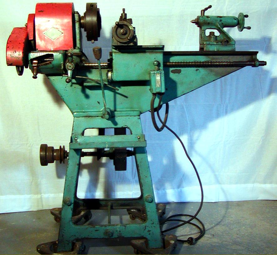
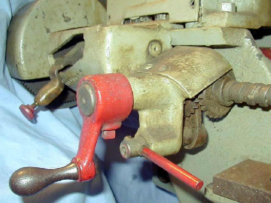
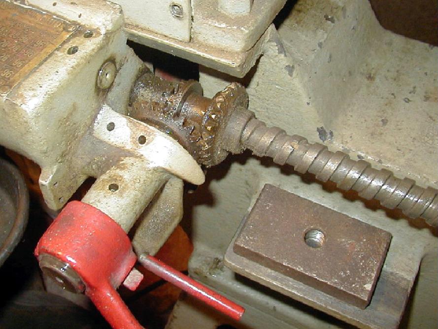
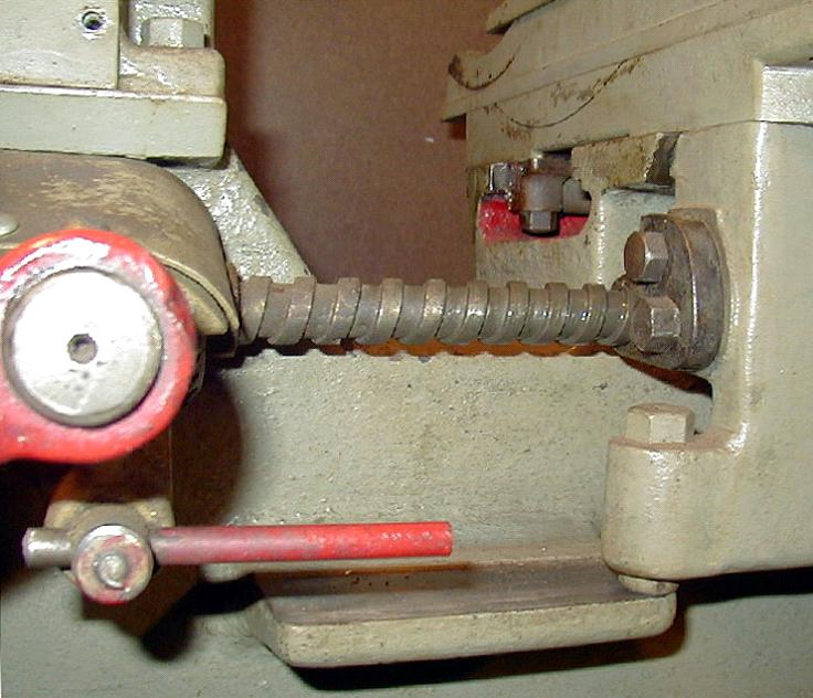
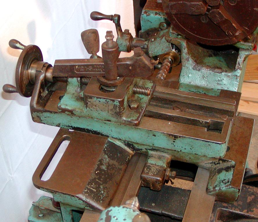
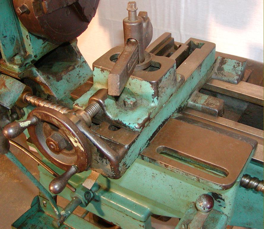
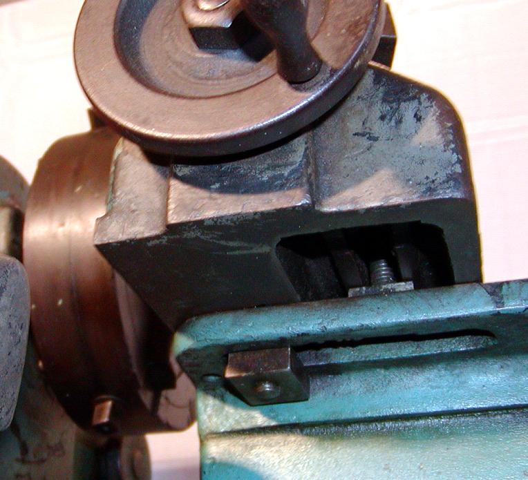
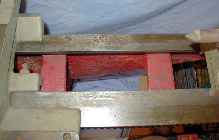
The Artisan, with a useful 24 inches between centres, demonstrates a manufacturer revelling in a dichotomistic mixture of simple and complex design, cost cutting and needless extravagance in the materials employed. The main features included: a very deep-section, flat-topped, V-edged cantilever-form bed with a 16-inch capacity gap and the saddle guided on the English "narrow-guide" principle with a vertical way set inboard of the front V; a gear-driven headstock, devoid of any lubrication system - yet with a large (17/16") bore spindle running in very substantial bearings braced by deep ribs upon which rested a sheet metal cover. A plain apron, devoid of any controls and fitted with a "full-nut" for the leadscrew with the latter a "barley-sugar" coarse-spiral of 2 t.p.i. The carriage could be propelled along the bed by either a hand-cranked (90-degree drive) bevel box (with bronze gears) or by a full screwcutting and feeds gearbox. A single cross-slide was fitted, running on old-fashioned square ways and driven by an exposed, Whitworth-form thread that lacked a micrometer dial. Even the tailstock contrived to be different, with the casting left open at the rear to reveal the sliding spindle; although this left a proportion of the barrel unsupported, it did have the distinct advantage of letting the locking clamp pull down on an uninterrupted slot and so reduce the chances of a split casting as the unit gradually wore in service.
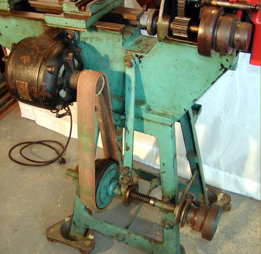
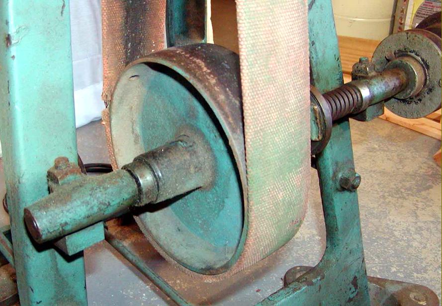
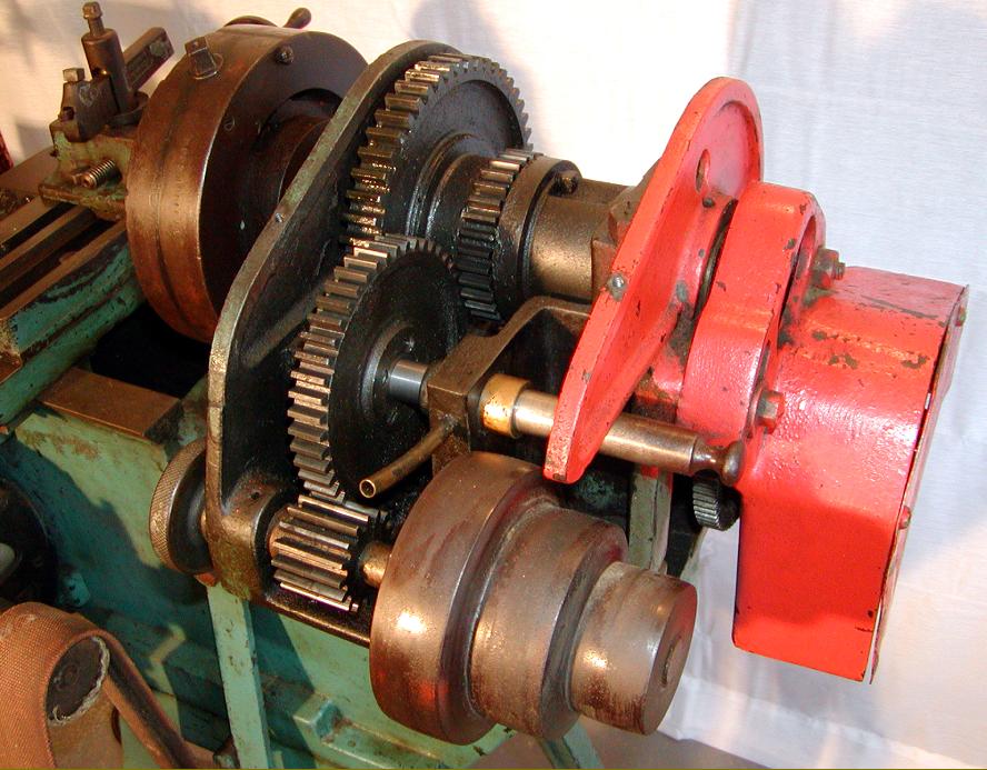
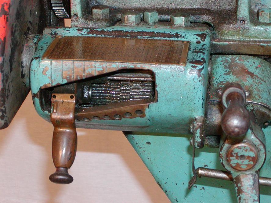
At a time when almost every other lathe of a similar size was supplied with a loose countershaft that required bolting to a wall or the ceiling, the Artisan could be supplied in a ready-to-run form mounted on a well braced, motorised stand. The built-on countershaft was well engineered with a motor bolted to the rear face of the bed driving down (with a suitable wide flat belt) to a shaft running in bronze bearings. A simple cone clutch was built into the large driven pulley and operated by a handy, front-mounted lever connected to a rod that passed through the bed to connect with a linkage at the back.
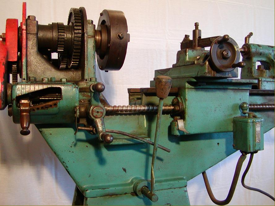
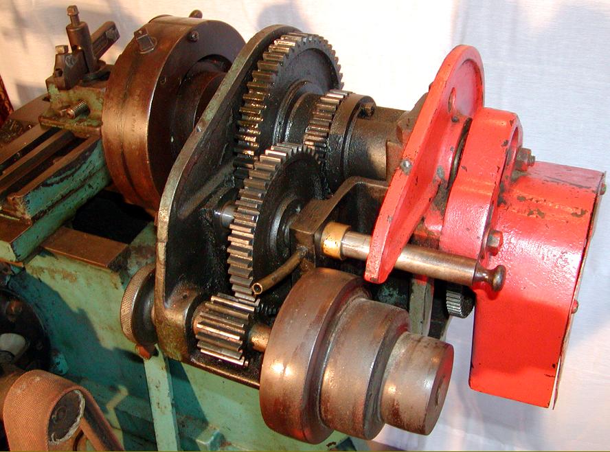
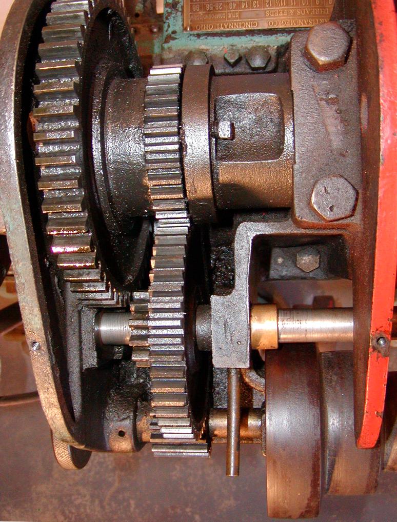
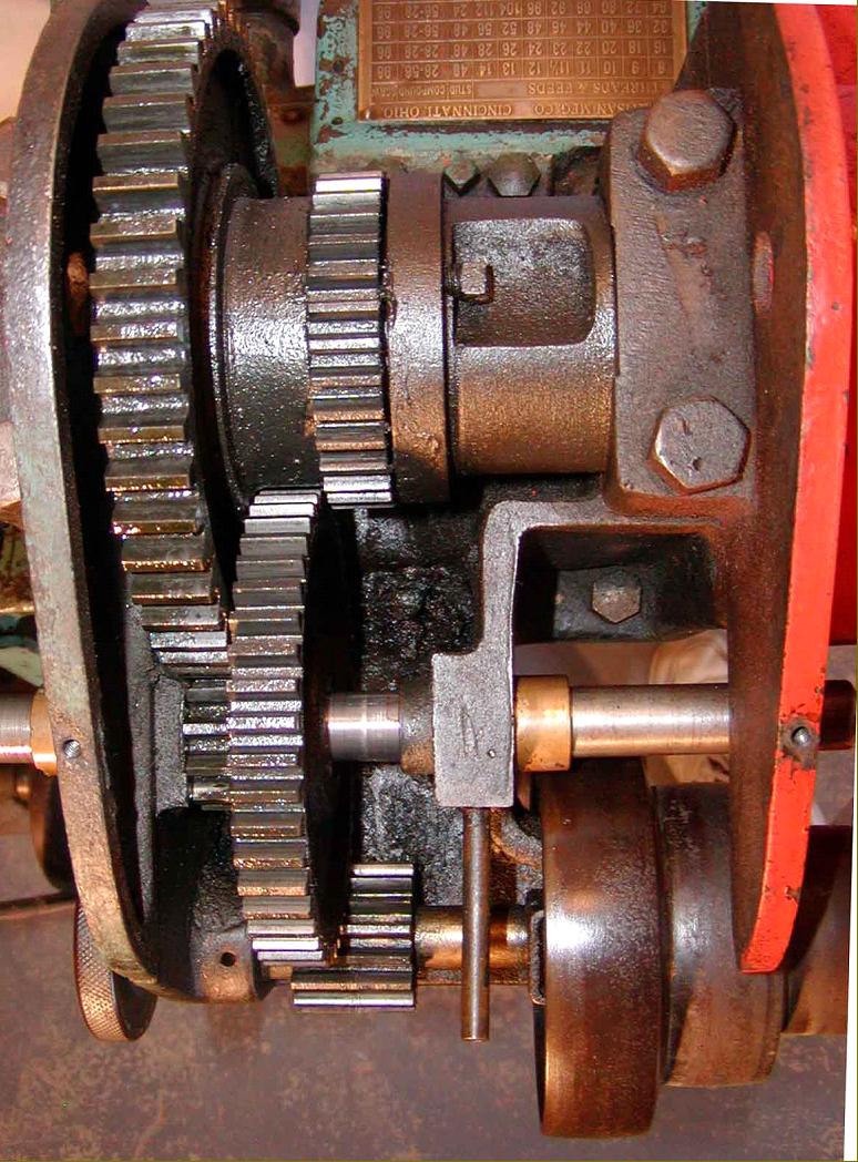
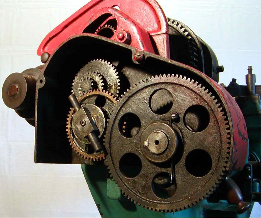
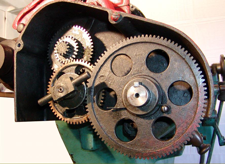
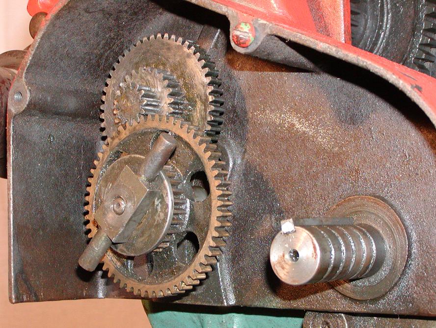
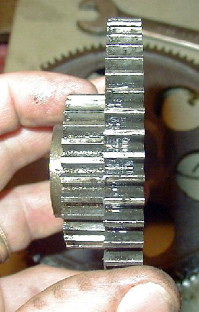
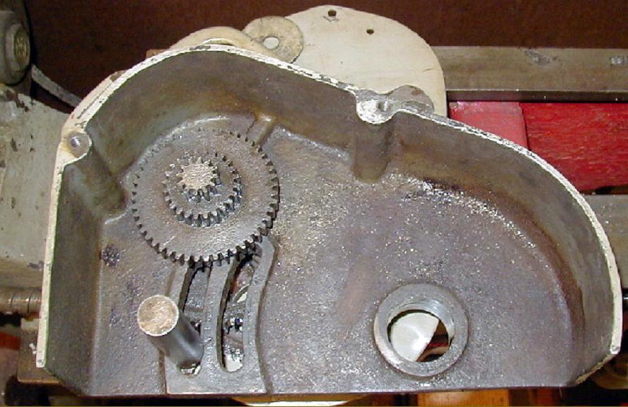
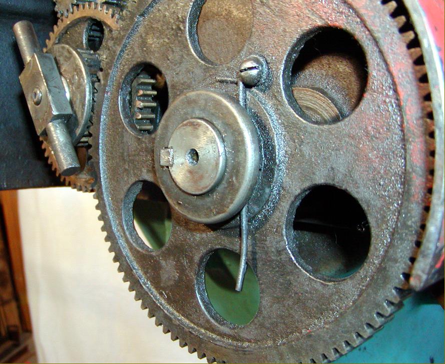
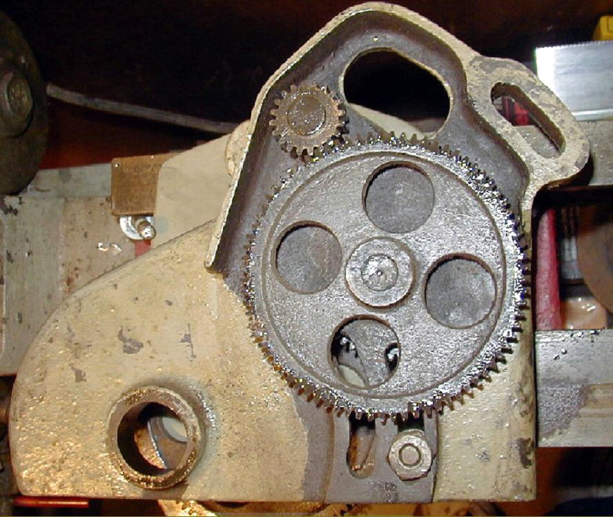
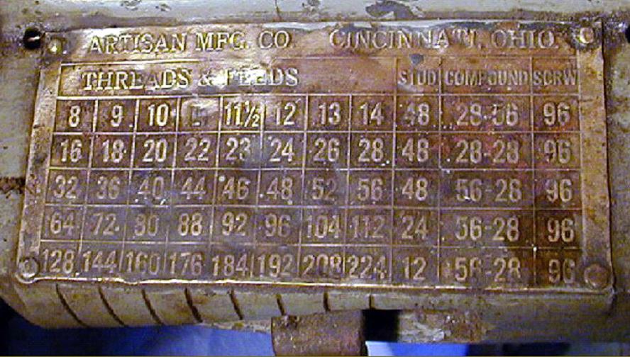
Instead of a separate bracket (banjo) to carry the changewheels the Artisan used a complex system that utilized the inner part of the cast-iron gear guard. The cover was fitted with both fixed and sliding studs to carry the gears (some of which were in bronze) with the complete assembly arranged to pivot on a bolt mounted to the rear of the headstock spindle; as this gave the effect of an ordinary tumble-reverse mechanism, moving the cover in the appropriate direction caused the rotation of the leadscrew to be reversed. It was also possible, with some effort, to alter the ratio between spindle and screwcutting gearbox input shaft: the large (96 tooth) "screwgear" on the end of the gearbox shaft was held in place by a quick-release spring clip; by removing this gear room was provided for the stud of an intermediate compound gear (of 28/56 teeth) to be placed in either of two slots and adjusted to engage with any of the three gears on a triple-pinion stud gear (with 12, 24 and 48 teeth) located in the upper left-hand section of the cover. A set of five grooves, turned into the gearbox input shaft, allowed the large final-drive gear to be positioned correctly in relation to the others - it being necessary only to drop the gear's spring retaining clip into the correct slot.
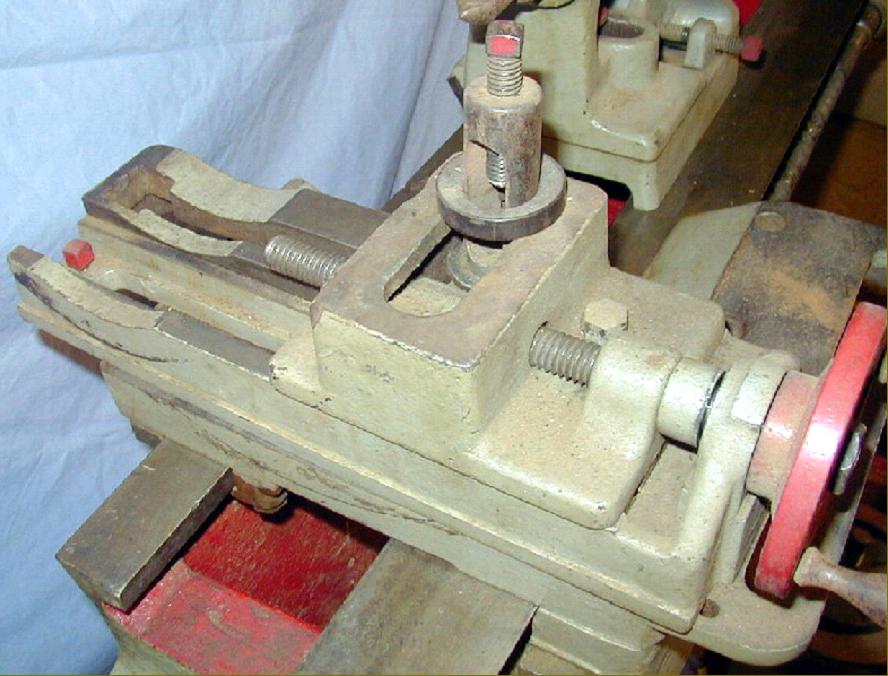
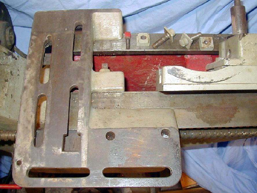
To obtain the necessary clearance, the gear could be fitted with its pronounced central boss facing either inwards or outwards. Yet more individuality was displayed in the location of the leadscrew "nut", this being fastened not in the centre of the apron (as on most lathes) but bolted to its left-hand face. It appears that the designer, fearful of bending loads overcoming the rather thin casting when turning large diameters in the gap, incorporated a thrust plate on the front face of the bed against which an adjuster nut, screwed through a boss on the front left corner of the apron, could bear. The idea was reminiscent of that used on some Barnes lathes, where the top of the carriage-feed rack was used in a similar fashion.
Fitted with sets of slots at right angles to each other, the saddle carried a single, bolt-on cross slide (there was no swivelling top slide) - the idea being, presumably, to allow the cutting tool to be moved outwards so as to reach the periphery of large diameter work turning in the bed's very deep gap. The slide was driven by a crude, exposed Whitworth-form screw and, though no micrometer dials have been found on early machines, the inner boss of the handwheel was formed with the possibility of being engraved for this purpose; in addition, the top of boss forming the handwheel thrust face had a raised section that might well have been intended for a zero line.
Dating the lathe remains a puzzle - the writer's best guess being a production run starting in the early 1920s and finishing in the mid 1930s. Bearing witness to the fact that the lathe must have remained in production some years - and sold in reasonable numbers - were the number of changes made to its specification in a Mk. 2 version and the continued development by Rocky Mountain Steel in the Mk. 3. Modifications incorporated into the former included an increase in the centre height to just under 6-inches; a variety of longer beds; different stands (including a cast-iron version closed in at the front but open at the rear); a proper compound slide rest with the cross-slide ways changed to a more modern V-type; the top-slide base graduated in degrees and a T-slot provided to hold a standard, lantern-type toolpost. In addition, zeroing micrometer dials were fitted to the top-slide, cross-slide and carriage handwheel - with the latter featuring a vernier scale - a fitting seldom seen on even the most expensive toolroom lathes. The saddle-to-bed fit was adjusted by tapered gib strips and the unusual "carriage-gap support" given a much more substantial bronze foot (rather than the bolt used on earlier examples). Most unusually (though perhaps not unexpected on this strange lathe) the leadscrew had a double start, left-hand Acme-form 2 t.p.i. thread.
Fitted with a different bed of much reduced depth (though retaining the same saddle ways), the Mk. 3 Rocky Mountain version carried the cast-in word "bench" - and was fitted with a neat, all-V-belt swing-head countershaft mounted at the rear of an extended-depth headstock-end bed foot. Although the rest of the lathe appears to have been left largely unchanged, in order to increase the travel of the cross-slide, a conventional "distance piece" (in bronze) was bolted to the front of the (all-new) casting to carry its feed screw and micrometer dial.
If you have an Artisan lathe, know anything about the Company or come across advertisements featuring the machine, the writer would be interested to hear from you.
Artisan photographs continued here Artisan Mk. 2 Artisan Mk. 3
|
|