|
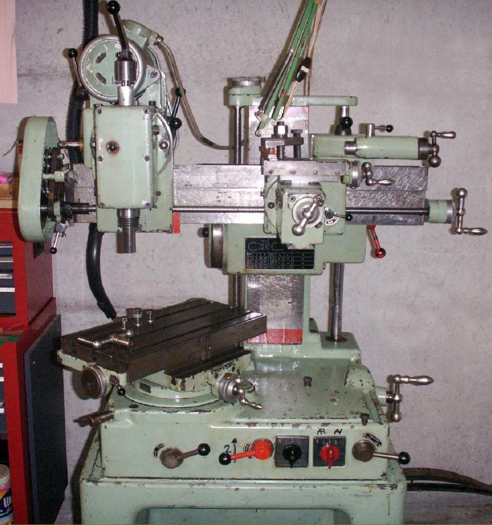
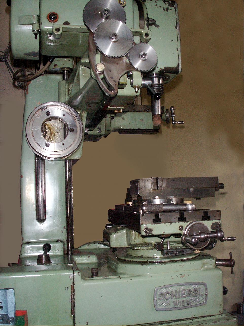
Manufactured by Schiessl & C° in Wien (Vienne - Vienna) Austria during the late 1950s and 1960s, the Schiessl is little known and must have sold in limited numbers. Of considerable sophistication, ingenious construction and exemplary quality, it was intended to function as seven machines in one - as a screwcutting centre lathe, a vertical lathe, horizontal borer, horizontal and vertical miller, a drill and, with the addition of other accessories, a slotter or shaper. One experienced user reports that this was an accurate and smooth-running machine with a particularly easy change from one function to anther.
Occupying an area of approximately 1000 mm x 1000 mm x 1200 mm and weighing 370 kg, the machine was of unique arrangement and versatility - though it did share some features with the English Metalmaster and Labormil machines. Its similarity to other better-known models of combination machine such as the Hommel, Meyer and Burger, Rindis, Scope, Sacia, and Murad was limited.
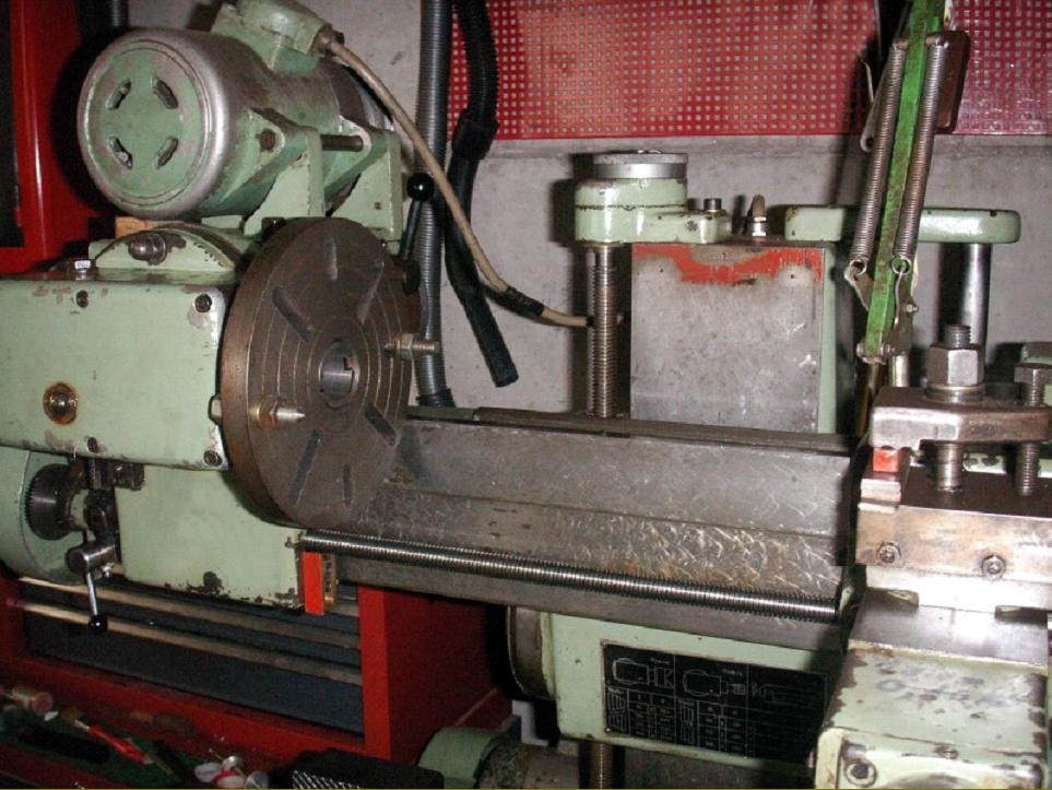
Constructed on a box-form cast-iron base, the Schiessl was arranged with a vertical column of rectangular form machined on its front face to take an elevating cross beam, around 29 inches (740 mm) long, that formed the bed of a 3.8" x 19" (95 mm x 400 mm) "lathe".
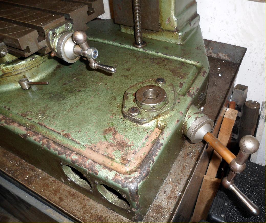
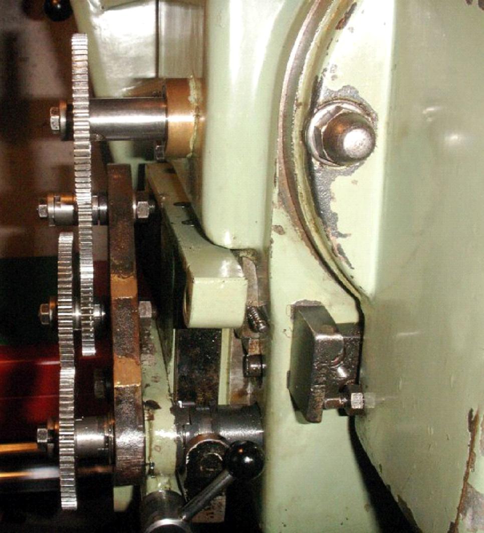
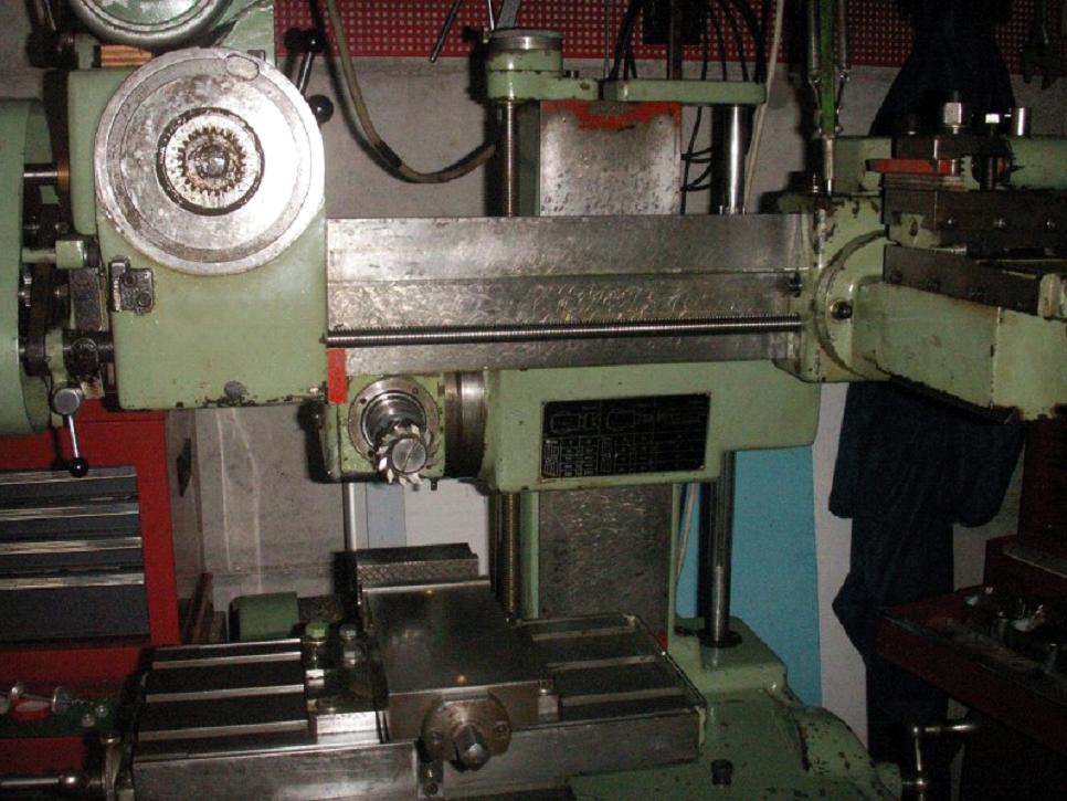
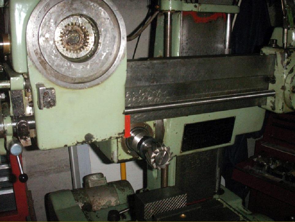
At its left-hand end the horizontal beam carried a swivelling "headstock" that doubled as both a vertical milling head and, when set horizontally, as a lathe headstock - the tailstock running on ways machined into the rear of the beam. The beam could be elevated through around 250 mm either by hand or power. In the former case a 3 mm pitch feed-screw was provided with its wheel and 0.010 mm division micrometer dial carried on a shaft protruding from the right-hand face of the base and the drive passing through bevel gears. Power lift was from a motor fixed externally to the rear of the cabinet and a clutch-engaged gear train driving an unprotected vertical splined shaft that emerged from the back right-hand corner of the base. The maximum clearance beneath the spindle nose was 320 mm and the minimum 70 mm, the head being lifted and lowered. With great ingenuity the headstock performed yet another function with its front section (that swivelled around its internally splined drive gear) able to be removed and fitted to a second drive socket mounted on the left-hand face of the rise-and-fall casting - where it was used to drive the horizontal milling arbor. However, an earlier version of the machine has been discovered that differed from the previous description: this had base and column cast as one with elevation of the cross beam by a hand-screw only - though the latter could be rotated around its central point, not a feature fitted to the later version.
Running in taper roller bearings, the spindle was bored through 25 mm, had a No. 2 Morse taper socket, a DIN 800 nose and could take ER25 collets from 2 to 20 mm. Spindle speeds, driven by a top-mounted 0.75 kW motor through V-belts and 4-step pulleys, ran from 75 through 125, 200, 300, 550, 900, 1300 to a usefully high 2000 r.p.m. The earlier machine appears to have had a different spindle end fitting, a shallow-taper sleeve, resembling a No. 30 INT, being machined on nits inside with a No. 2 Morse taper.
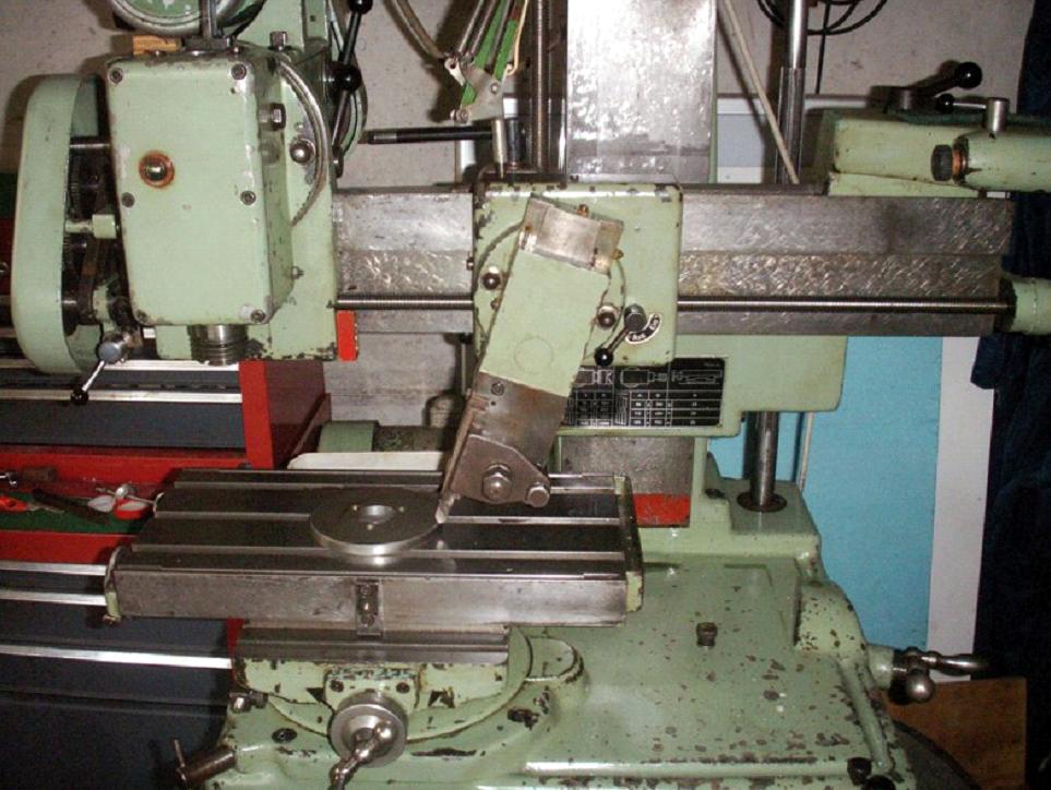
When in use as a lathe a combined "carriage and compound slide rest" assembly was fitted, the cross-slide section doubling as the overarm of the horizontal miller with its underside machined to take the cutter-arbor support bracket and its top a lathe like tool slide. An alternative fitting, shown on a second example of the machine lower down the page, was a tool-slide that bolted directly to the face of the carriage with a screw that could be driven by hand or power from the horizontal leadscrew - this facility enabling the device to be used for slotting either vertically or at an angle.
A conventional leadscrew was used to drive the carriage along the bed, a handwheel and micrometer dial being provided at the tailstock end and changewheels at the other. Threads from 0.3 to 7 mm pitch could be generated, as well as 4 to 60 t.p.i. English and Module 0.3 to 1.5 - though in each case suitable sets of changewheels had, of course, to be mounted.
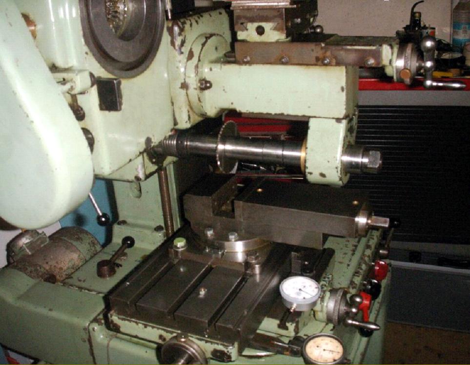
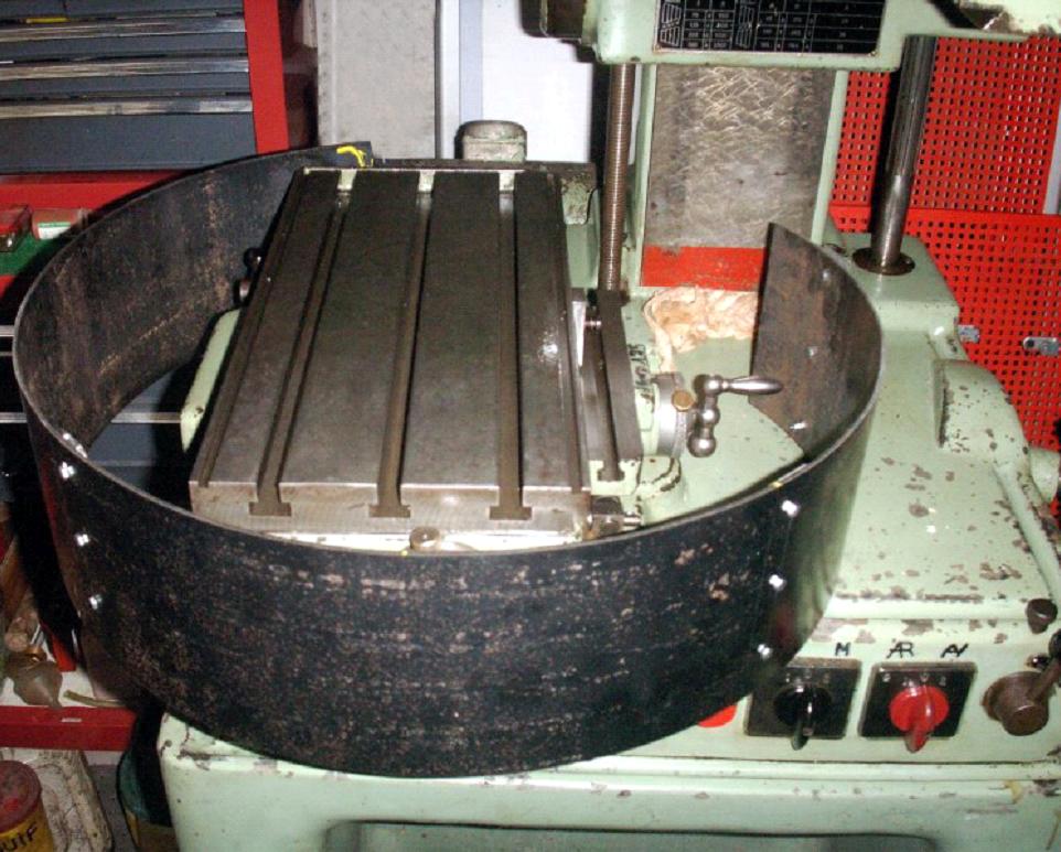
Fitted on a rotating base at the front left-hand side of the stand was a 400 x 200 mm compound table equipped with three 11.56 mm wide T-slots on 60 mm spacing. Travels, measured by finely engraved and decently sized micrometer dials, were reasonable: 175 mm longitudinally and 130 mm across. Unusually, the table feed-screws were each of a different pitch: the longitudinal being 3 mm with each micrometer dial divisions showing a travel of 0.01 mm while the lateral was finer at 1.75 mm, with dial graduations indicating a movement of 0.05 mm. The table could be rotated by hand or, astonishingly, under power in both directions at rates of 23, 36 or 55 revs/min. With the toolpost angled downwards (at a maximum of 45 degrees each side of vertical) the machine could be set up as a vertical lathe able to turn both internally and externally - possibly the only multi-function machine ever able to achieve this arrangement. The earlier version of the machine was built onto a base-plate of different design that housed a train of gears to turn the compound table by hand, the operating handle being on the right hand side of the top surface with its shaft fitting vertically into a boss split so that it could be clamped in place or removed when not in use. It is likely (but not certain) that this model omitted the power rotary drive.
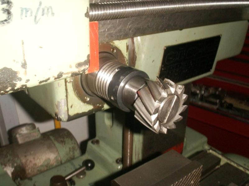
When set up for horizontal milling the speeds available were set at 65, 110, 165, 310, 480 and 760 r.p.m. with the horizontal cutter arbour able to be moved a maximum distance of 260 mm above the table.
Should any reader have a Schiessl, or any literature about the Company's products, the writer (and owners of the examples below) would be most interested to hear from you..
|
|