email: tony@lathes.co.uk
Home   Machine Tool Archive   Machine-tools Sale & Wanted
Machine Tool Manuals   Catalogues   Belts   Books  Accessories

Denbigh Milling Machines

Denbigh Millers Page 2   Denbigh Millers Page 3 (Older Models)

Denbigh Lathes   Denbigh Drills   Denbigh Literature

Denbigh Mechanical Hacksaw

The Denbigh Engineering Co. Ltd. was based at Horseley Heath, Tipton, in Staffordshire, England and manufactured an extensive range of basic machine tools. Tipton, being halfway between Birmingham to the south east and Wolverhampton to the north west, was in the heart of the "Black Country", an area once heavily industrialised and a focal point of developments during the Industrial Revolution. Today the town is home to the Black Country Living Museum, a large, open-air affair with reconstructed buildings showing life as it was in a mid-1800s iron-working town - a real day-out treat for steam and engineering enthusiasts.
Describing themselves as "
Engineers, Machine Tool Makers, Mill Furnishers and iron Founders", Denbigh appear to have survived until at least the mid 1970s when, at a new address, Malcolm House, Batsford, Moreton-in-Marsh, Gloiucestershire, they were issuing a simple one-sheet price list showing rebranded Elliott-Progress geared head 4E and 5E pillar drills. However, also listed on Company literature was a works address, Stratford Road, Shipton-on-Stour in Warkshire, with a note that they were manufacturers of Pillar Drilling, Horizontal Milling and Power Hacksaw Machinery.
In pre-WW2 years Denbigh's output consisted of the Type B and "New B" heavy horizontal milling machines, the lighter Type H horizontal millers in a number of configurations -  H1, H2, H3 and H4 - for bench mounting or fitted to floor-standing cast-iron columns, a wide variety of industrial bench and pillar drills, a foot-lever press, wet and dry tool grinders, two models of metal spinning lathes, two sizes of what the makers termed "polishing lathes" (today they would be regarded as simple polishing stands) and the Company's patented "Hand Jolt Ram", this being an effective hand-operated sand moulding machines for use in foundries. By the mid 1960s the range had been considerably trimmed and, although no lathes were produced, the "Swiftcut" metal-cutting donkey saw had been introduced, a wide range of drills was still manufactured as well as manual and air-operated fly and lever presses and a number of simple, cheaper horizontal milling machines including the Type C, Type D, Type D3, Type M, Type J.P., Type J.V.S, and the Type J.P.V.S. - many being of simple design, reasonably priced and of and so finding their way into technical colleges and apprentice training schools.
Long a common practice in many spheres of industry, Denbigh also made batches of un-branded milling and other machines for distribution by third parties. In some cases the millers differed from the regular Denbigh specification with some obviously manufactured to a customer's particular requirements.
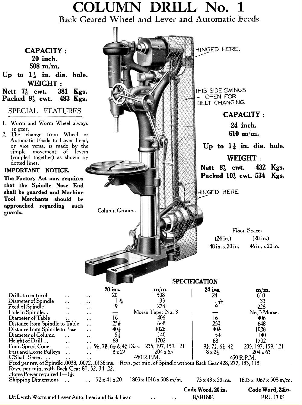
Denbigh drills were of an absolutely conventional design, their origins going back to Victorian times and little developed even after WW2 - though a few more modern bench and pillar drills with enclosed V-belt drive, the K Series, had been introduced during the 1950s.
Denbigh had their own foundry - unsurprising, as they were in the very heart of the original English iron founding area - and turned out castings to a very high standard. All their machine tools were heavily built, capable of absorbing continuous industrial use and were widely exported. Although their original design of "swan-neck" drill might appear hopelessly old-fashioned, they worked (and still do) extremely well with little to go wrong and having reserves of power. One model in particular, the
No.1, lasted almost until the company closed in 1970, a testament to its simple design and rugged construction.
Not so popular were the Denbigh milling machines with these, in later years, being aimed at the school and training markets where great strength and weight were not considered necessary. Fit and finish of these models was also not to a particularly high standard, again, not a serious consideration when price was the prime consideration..

Denbigh "C" Type fitted with the optional 2-inch stroke Slotting Head

Of all their various models, the Type C is the Denbigh  that appears to have to survived in the greatest numbers - although the "D" type was also popular and designed to compete at the less-expensive end of the market, as its strictly functional appearance would confirm. To save money, early versions of the D were  bereft of even a table-feed micrometer dial, though, thankfully, this was included as standard on later machines.
Several models of the C were available, all constructed around the same basic column: the "C1" and "C2" had tables with a working surface of 34" x 10" with a 22.5" travel whilst those on the "C3" and "C4" were some 12" longer - but no wider - and with a longitudinal travel of 34.5". The tables could be supplied either fixed or with a pivoting motion allowing an angle of 45 degree either side of the centre line - in the latter case the table travel was increased by 2" for all models - and the machine described as a "Semi-Universal". The cross feed on all models was 7.5" and the vertical adjustment of the knee 16" on the small-table models - and 18" on the larger.
Early machines had overarms 3
3/8" in diameter, later machines, from around 1956, were fitted with ones some 5/8" larger.
The drive system employed two endless chrome-leather-faced plastic flat belts; one, 3" wide, ran from the standard-fit 3 hp 940 rpm motor to a ball-bearing countershaft in the base of the miller whilst the other, 2.5" wide, ran from the countershaft up to the 3-step cone pulley which drove the taper-roller bearing No. 4 Morse taper horizontal spindle.
The whole of the countershaft system was balanced against two large springs and could be slackened and lifted to aid belt-position changes by the action of two levers at the rear of the machine. To obtain usefully slow and powerful speeds the No. 4 Morse taper, nine-speed, taper-roller bearing spindle was given a lathe-like "double-back gear", running on ball bearings. Power feed to the table - which worked only in one direction - was derived from a chain drive on the main spindle to a 4-speed gearbox mounted on the right-hand side of the column. Spindle speeds for all versions of the Model C were the same: with back-gear set in its first position: 13, 25 and 51 rpm were available and in its second position: 36, 71 and 143 rpm. Without back-gear the speeds rose to 100, 200 and 400 rpm - hardly fast, but just about adequate.

Denbigh "C" with the standard-fit, double-slotted  bracing bar.

Denbigh "C" with a 2x geared-up No. 3 Morse taper vertical head and table "quick-return" attachment.

Denbigh D Type horizontal miller with standard countershaft drive. The double reduction backgear was engaged by the two levers on the left-hand face of the main column.
The D Type was one of the largest machines made by Denbigh and available in four models: D1, D2, D3 and D4.
D1 34" x 10" non-swivel table - 22.5" of travel
D2 34" x 10" swivel table - 25.25" of travel
D3 46" x 10" non-swivel table - 34.5" of travel
D4 46" x 10" swivel table - 37.25" of travel
The table drive used a 4-speed gearbox, chain-driven from the main spindle, that gave feed rates of: 0.027,  0.021,  0.013 and 0.01" per revolution of the cutter; an extra sprocket was supplied with the machine that gave four alternative, rather slower rates of : 0.013,  0.010, 0,007 and 0.005". The non-swivel table models had power feed in one direction only - whilst those with a swivel table (the "Universal" enjoyed power in both directions as standard.
The ordinary drive system (a variable-speed drive was optional) employed two endless chrome-leather-faced plastic flat belts; one, 2" wide, ran from the motor to a ball-bearing countershaft and could not be adjusted - it was pre-tensioned at the factory and presumably had to be replaced if it ever started to slip. The second belt, 2.25" wide, ran from the countershaft up to a 3-step cone pulley which drove the 3% nickel-chrome steel, taper-roller bearing, No. 4 Morse taper horizontal spindle.
The whole of the countershaft system was balanced against two large springs and could be slackened and lifted to aid belt-position changes by the action of two levers at the rear of the machine. As an aid to heavy-duty metal removal, the miller was fitted with a two-stage, lathe-like backgear assembly. In "open gear" (without the backgear engaged) speeds of 180, 360 and 720 rpm were available; with the first stage of the backgear in speeds were reduced to 60, 120 and 240 rpm and with the gear in its lowest-ratio drive 19, 38 and 76 rpm. The variable-speed drive version was fitted with an expanding-and-contracting pulley assembly exactly like that employed on the Type C and M machines; it retained the double-backgear assembly as well and in open drive spanned 250 to 720 rpm; in backgear first stage 90 to 260 rpm and in backgear second stage 30 to 90 rpm.
A special model was manufactured, based on the D3, with an air-hydraulic table drive to aid automatic production processes; an air supply of 30 cubic feet a minute at a pressure of 100 psi was required to run the unit - this model is shown below.
Model D machines weighed between 25.75 cwt and 32.75 cwt and required a floor space of 70" x 60"..

Denbigh D Type horizontal miller with the optional self-motorised table quick-return attachment

Levers to unlock (2) and release (1) the countershaft belt tension prior to changing speeds.

A special model was manufactured, based on the D3, with an air-hydraulic table drive to aid automatic production processes; an air supply of 30 cubic feet a minute at a pressure of 100 psi was required to run the unit

Denbigh Model M
The 1400 lb Model M was Denbigh's smallest miller that had screw feed to both table movements. It was advertised as being "
A low-cost machine for high production on small and medium work." and a smaller version of the Model D. Like its bigger brother, the CVS, the Model M was fitted as standard with a variable-speed drive unit that, equipped with a 2 hp, 1400 rpm motor, gave speeds  from 65 to 245 rpm in the 4 : 1 ratio backgear and 260 to 980 rpm in open drive. The backgear was well engineered - all the gears were cut from steel, the shaft ran on ball bearings and the whole assembly was enclosed in an oil bath.
Only one table size was offered, 30.5" x 6
7/8", with a longitudinal travel of 16.5 inches and a cross feed of a (very inadequate) 3.75 inches. Fitted as standard was a 3-speed table-feed gearbox with rates of 0.0213, 0.0112 and 0.006 inches per revolution of the cutter.
The 3% nickel-chrome steel main spindle ran on taper-roller bearing and carried a No. 3 Morse taper nose, into which fitted a 1-inch diameter cutter-holding mandrel. The overarm was a 3-inch diameter steel bar.

Denbigh Millers Page 2   Denbigh Millers Page 3 (Older Models)

Denbigh Lathes   Denbigh Drills   Denbigh Literature

Denbigh Mechanical Hacksaw

Denbigh Milling Machines

email: tony@lathes.co.uk
Home   Machine Tool Archive 
Machine-tools Sale & Wanted
Machine Tool Manuals   Catalogues   Belts   Books  Accessories